Phase locked loop circuit and phase locked loop control method

a phase lock and loop technology, applied in the direction of phase difference detection, automatic control of pulses, electrical equipment, etc., can solve the problems of affecting the waveform of the reproduced rf signal more severely, the phase lock of the rf signal may fail, and the pll circuit cannot quickly complete the frequency pulling-in processing

Inactive Publication Date: 2007-03-01
SAMSUNG ELECTRONICS CO LTD
View PDF5 Cites 12 Cited by
  • Summary
  • Abstract
  • Description
  • Claims
  • Application Information

AI Technical Summary

Benefits of technology

[0018] An aspect of the present invention provides a phase locked loop circuit and a phase locked

Problems solved by technology

However, since the PLL circuit shown in FIG. 1 does not take into consideration a frequency error between the sampled RF signal and the sampling clock, the PLL circuit cannot quickly complete frequency pulling-in processing.
As a spot size of an optical beam becomes larger than a pit length, the

Method used


Image

  • Phase locked loop circuit and phase locked loop control method
  • Phase locked loop circuit and phase locked loop control method
  • Phase locked loop circuit and phase locked loop control method

Examples


Embodiment Construction

[0046] Reference will now be made in detail to the present embodiments of the present invention, examples of which are illustrated in the accompanying drawings, wherein like reference numerals refer to the like elements throughout. The embodiments are described below in order to explain the present invention by referring to the figures.

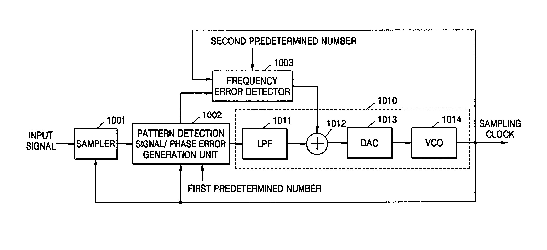
[0047]FIG. 7 is a functional block diagram of a phase locked loop circuit according to an embodiment of the present invention. Referring to FIG. 7, the phase locked loop circuit includes a sampler 701, a pattern detection signal / phase error generation unit 702, and a sampling clock generation unit 710.

[0048] The sampler 701 samples an input signal according to a sampling clock outputted from a phase locked loop circuit. The input signal may have the shape of a sinusoidal wave, and the sampler 701 may sample and output the amplitude of the input signal at a rising edge of the sampling clock.

[0049] If the sampled input signal outputted from the sampl...


PUM


Abstract

A phase locked loop circuit and a phase locked loop control method in an optical disc reproducing system having a high ISI condition is capable of detecting a phase error and a frequency error of an input signal based on a pattern, such as a sync pattern, having a predetermined uniform distribution over an entire range. The phase locked loop circuit includes a sampler which samples an input signal according to a sampling clock output from the phase locked loop circuit; a pattern detection signal/phase error generation unit which generates a pattern detection signal indicating the detection of a predetermined pattern, detects a phase error between the sampled input signal and a zero crossing point of the input signal if the sampled input signal output from the sampler has the predetermined pattern, and outputs the detected phase error, and a sampling clock generation unit which generates the sampling clock based on the pattern detection signal and the phase error, wherein the predetermined pattern is a pattern which is uniformly distributed over the entire range where the input signal can be inputted.

Description

CROSS-REFERENCE TO RELATED APPLICATIONS [0001] This application claims the benefit of Korean Patent Application No. 2005-73448, filed on Aug. 29, 2005, in the Korean Intellectual Property Office, the disclosure of which is incorporated herein in its entirety by reference. BACKGROUND OF THE INVENTION [0002] 1. Field of the Invention [0003] Aspects of the present invention relate to a phase locked loop (PLL) circuit and a phase locked loop control method, and more particularly, to a phase locked loop circuit and a phase locked loop control method suitable for a high density optical disc reproducing system. [0004] 2. Description of the Related Art [0005] Optical disc reproducing systems reproduce data recorded on optical discs such as compact discs (CDs), digital versatile discs (DVDs), blue-ray discs (BDs), and high definition (HD) DVDs. Optical disc reproducing systems for BD and HD-DVD systems are referred to as high density optical disc reproducing systems. [0006] Optical disc repr...

Claims


Application Information

Patent Timeline
IPC IPC(8): H03D3/24
CPCH03L7/10H03L7/091H03L7/113
Inventor ZHAO, HUIPARK, HYUN-SOO
Owner SAMSUNG ELECTRONICS CO LTD
Why Eureka
Try Eureka