Image signal processor and image signal processing method

a signal processor and image technology, applied in the field of image signal processor and image signal processing method, can solve the problems of amplifying a noise component, deteriorating s/n, and affecting the performance so as to achieve the effect of enhancing the functionality of the image signal processor and the image signal processing method

Inactive Publication Date: 2007-03-01
MAXELL HLDG LTD
View PDF5 Cites 12 Cited by
  • Summary
  • Abstract
  • Description
  • Claims
  • Application Information

AI Technical Summary

Benefits of technology

[0014] According to the present invention, the facility of the image s

Problems solved by technology

However, noise by an analog circuit such as an image sensor is superimposed on a genuine image signal of a subject photographed by a camera.
Therefore, the signal processing for enhancing the resolution of an image consequently amplifies a noise component.
However, in the case of extrapolated interpolation, as shown in FIG. 7C, its noise amount is (1+α) Ns and its S/N is deteriorated.
As described above, conventional type signal processing fo

Method used


Image

  • Image signal processor and image signal processing method
  • Image signal processor and image signal processing method
  • Image signal processor and image signal processing method

Examples


embodiment 1

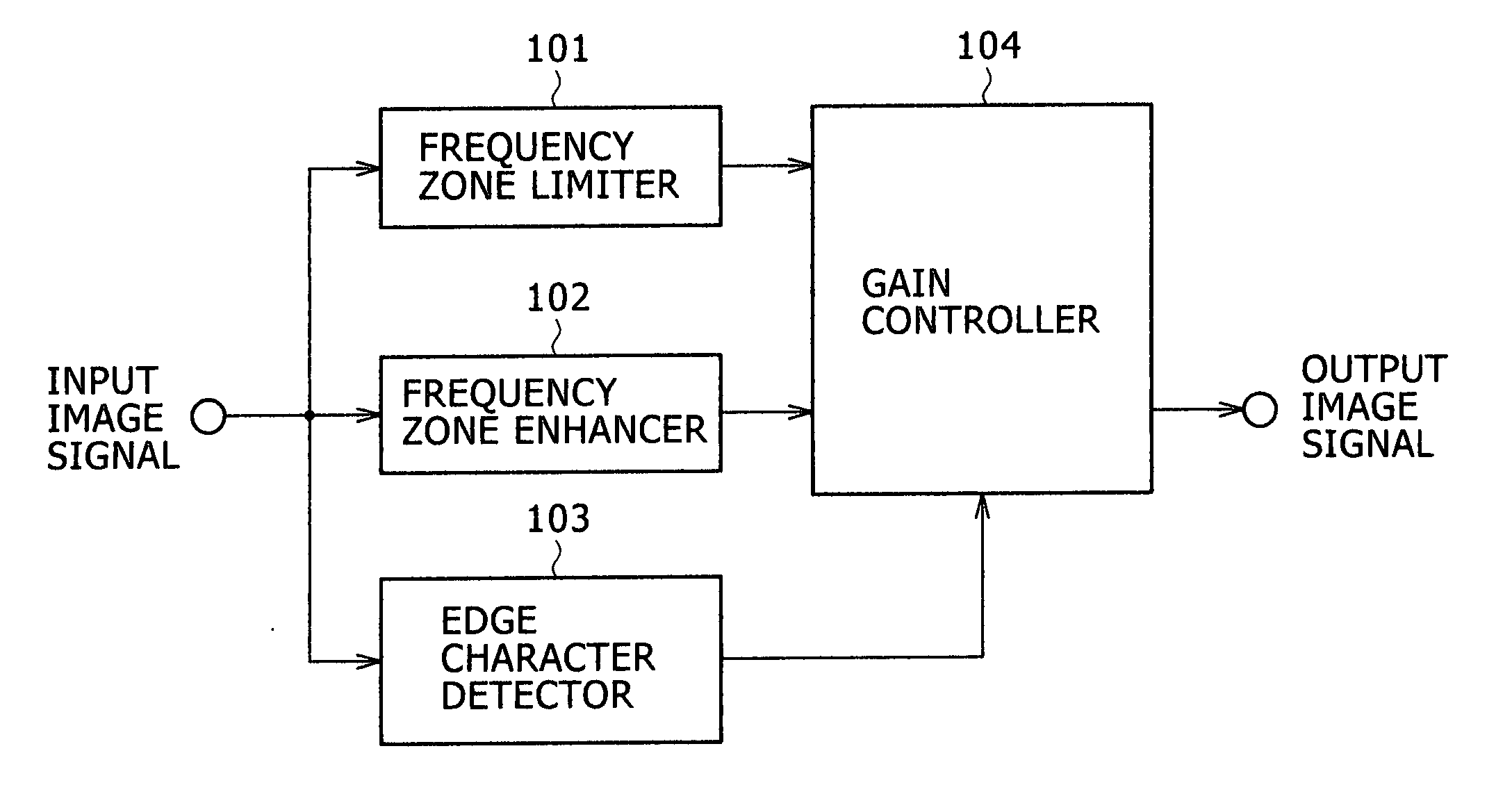
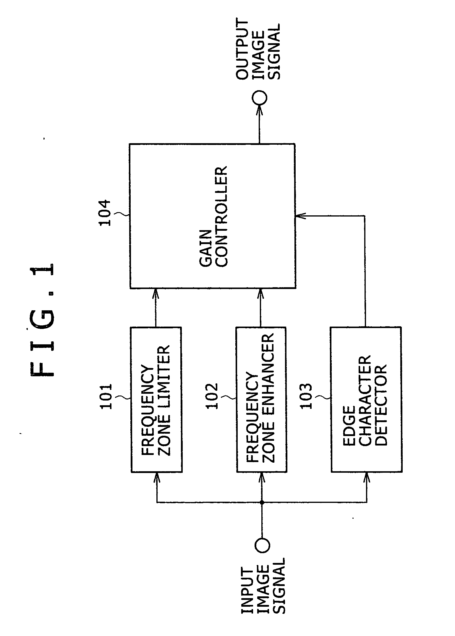
[0023]FIG. 1 is a schematic diagram showing an image signal processor in a best embodiment 1 of the present invention.

[0024] A frequency zone limiter 101 removes a noise component from an input image signal. For example, it is formed by a low-pass filter or a median filter.

[0025] A frequency zone enhancer 102 applies a resolution enhancing process to the input image signal, detects an edge of an object by adding overshoot and undershoot for example to the input image signal and compensates the input image signal. For example, the frequency zone enhancer is a part for generating an interpolated signal so that a frequency zone is extended when the interpolated signal is generated.

[0026] An edge character detector 103 detects a character of an edge of the object in the corresponding region based upon differential value information between a specific pixel and its peripheral pixel respectively in the input image signal or an absolute value of each signal level. For example, if a diffe...

embodiment 2

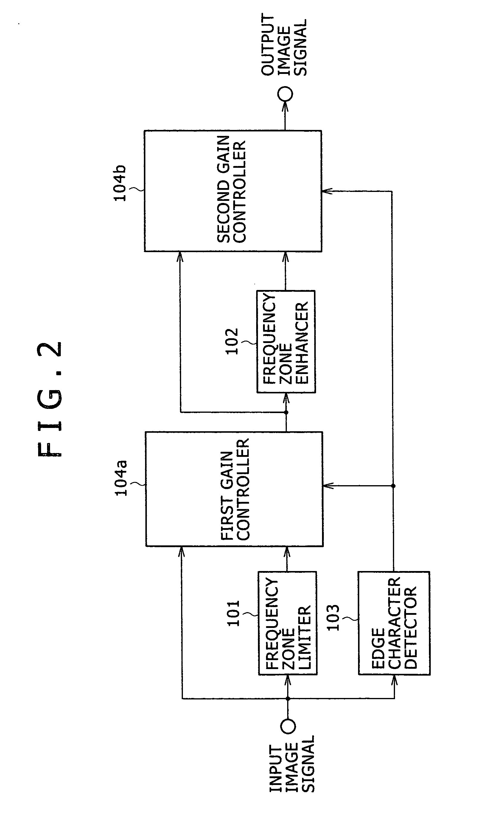
[0029]FIG. 2 is a schematic diagram showing an image signal processor equivalent to a best embodiment 2 of the present invention.

[0030] If a frequency zone limiter 101 and a frequency zone enhancer 102 are connected in series as shown in FIG. 2, the reduction of noise and a resolution enhancing process can also be effectively executed. For the difference in effect between the configuration shown in FIG. 1 and the configuration shown in FIG. 2, the following are conceivable. That is, in the configuration shown in FIG. 1, processing speed is faster, compared with that in the configuration shown in FIG. 2. In the meantime, in the configuration shown in FIG. 2, mounting is easier, compared with that in the configuration shown in FIG. 1. It need scarcely be said that the effect of the present invention is also acquired by changing the order of the frequency zone limiter 101 and the frequency zone enhancer 102 or applying only either.

[0031] It is needless to say that each unit configurin...


PUM


Abstract

The disclosed is to provide an image signal processor and its method in which the enhancement of resolution and the effective reduction of noise are compatible. The image signal processor is provided with an edge character detector that detects a character of an edge of an object, an image signal frequency zone limiter that executes a noise removing process, an image signal frequency zone enhancer that executes a resolution enhancing process and a gain controller that changes each intensity of the image signal frequency zone limiter and the image signal frequency zone enhancer according to an output result of the edge character detector.

Description

BACKGROUND OF THE INVENTION [0001] 1. Field of the Invention [0002] The present invention relates to an image signal processor and an image signal processing method. [0003] 2. Description of the Related Art [0004] For the art related to this technical field, for example, there are JP No. 113680 / 1998, JP No. 262158 / 1989 and JP-A No. 208038 / 2004. SUMMARY OF THE INVENTION [0005] Heretofore, signal processing for enhancing the resolution of an image has been realized by increasing the gain of a high-frequency signal using differential information with peripheral pixels. However, noise by an analog circuit such as an image sensor is superimposed on a genuine image signal of a subject photographed by a camera. Therefore, the signal processing for enhancing the resolution of an image consequently amplifies a noise component. [0006] For example, FIGS. 7A to 7C show an example described in the Patent Reference 1 when an extrapolated interpolated signal is generated. FIG. 7A shows input pixel...

Claims


Application Information

Patent Timeline
IPC IPC(8): G06K9/40
CPCG06T5/002G06T7/0085G06T5/20G06T5/003G06T7/13H04N1/387G06T5/00H04N5/208
Inventor NONAKA, YUICHINISHIZAWA, AKIHITO
Owner MAXELL HLDG LTD
Why Eureka
Try Eureka