Reducing light leakage and improving contrast ratio performance in FTIR display devices

a technology of contrast ratio and display device, which is applied in the field of flat panel displays, can solve the problems of system noise that compromises the signal quality, harms the display's quality, and noise, and achieves the effect of maximizing system noise reduction, reducing or eliminating the noise generated at the interface of the planar waveguide with any superadditional cladding layer, and tolerant of geometry errors

Inactive Publication Date: 2007-03-01
RAMBUS DELAWARE
View PDF74 Cites 55 Cited by
  • Summary
  • Abstract
  • Description
  • Claims
  • Application Information

AI Technical Summary

Benefits of technology

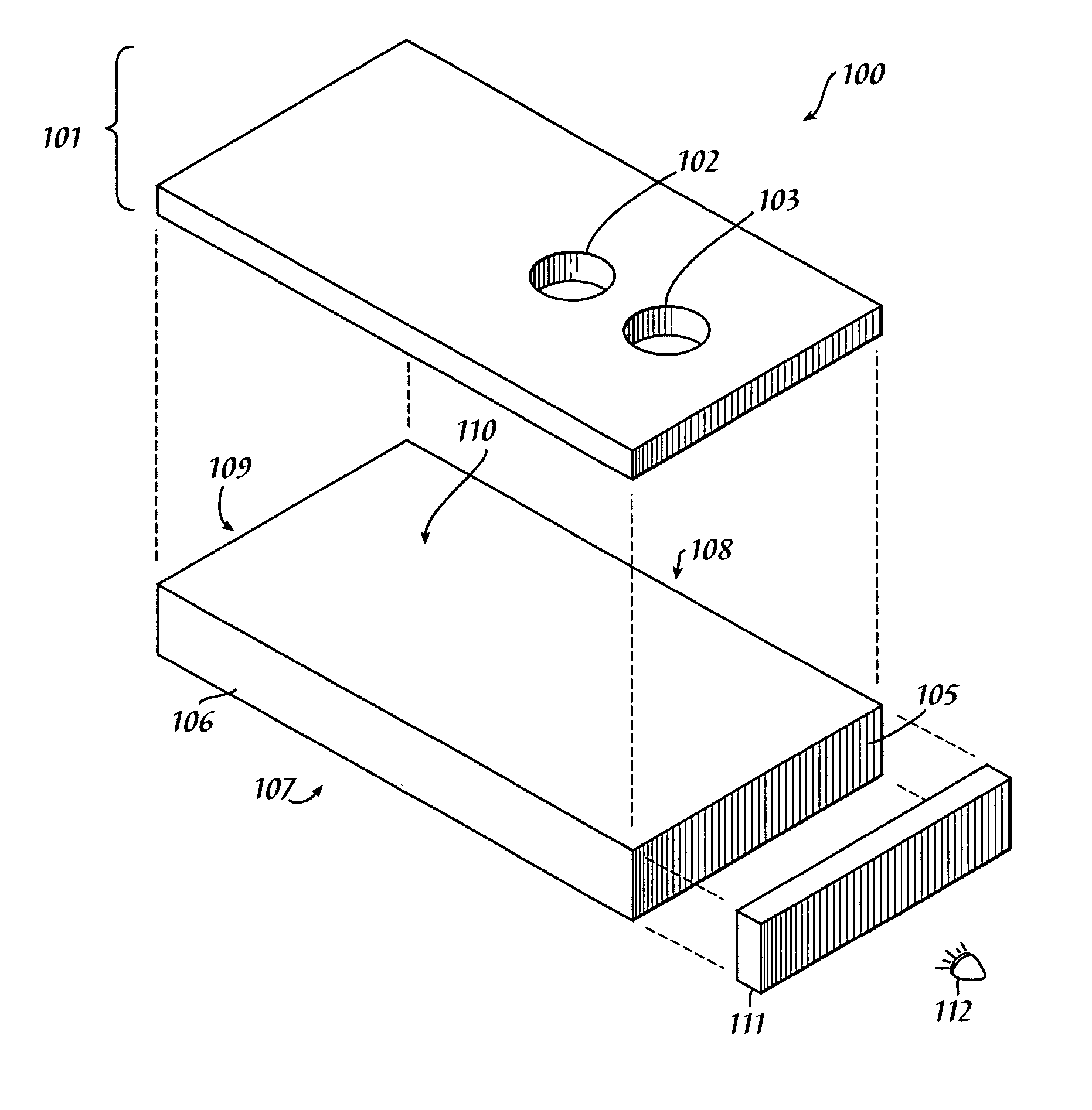
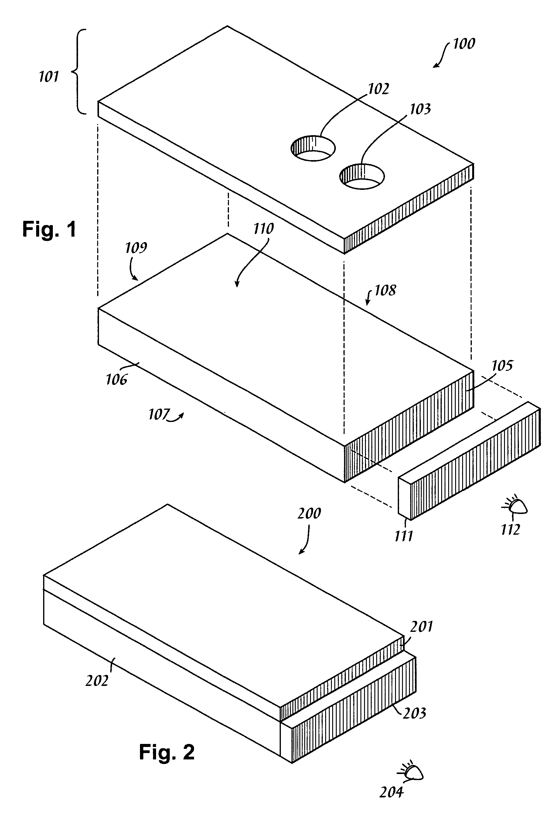
[0008] The problems outlined above may at least in part be solved by interposing material with a tuned refractive index between the light insertion face of the planar waveguide and the light sources that illuminate the waveguide. The interposition of this layer subtly restricts the admissible range of angles entering the planar waveguide. As a result of this restriction, the system becomes more tolerant of errors in geometry. Furthermore, noise generated at the interface of the planar waveguide with any superadded cladding layers can be reduced or eliminated, to the extent the interposed material approaches, matches, or exceeds the refractive index of the cladding material itself. The tuning of the interposed material's refractive index is optimized by simultaneously maximizing system noise reduction and maximizing the angular range of light that is allowed to enter the waveguide.

Problems solved by technology

At issue is the physical configuration to secure a suitable “off state” where light is intended to remain within the planar waveguide across a given pixel region.
If some light is always leaking (by spurious emission, frustration, or other cause) from the display (at the pixels, between the pixels, or in general), this constitutes system noise that compromises the quality of the signal.
Therefore, if an FTIR display emits noise (light when and where no light is supposed to be emitted), this harms the display's quality.
Noise arises when total internal reflection is frustrated when and where it should not be.
Different causes can give rise to such system noise, and in most displays more than one cause is operative to add to the noise level.
For example, the optical quality of the material selected for the planar waveguide has a direct bearing on noise.
For this reason, the waveguide will glow in proportion to the amount of scattering domains distributed within it, thereby raising the noise floor.
Other noise sources within FTIR systems do not have so straightforward a solution route.
These are sources of system noise (light leakage) that do not have a straightforward solution route.
The waveguide may exhibit errors in geometric construction (errors in parallelism between the three sets of opposing surfaces, and errors in orthogonality at all surfaces at a putative 90 degrees separation one from the other).
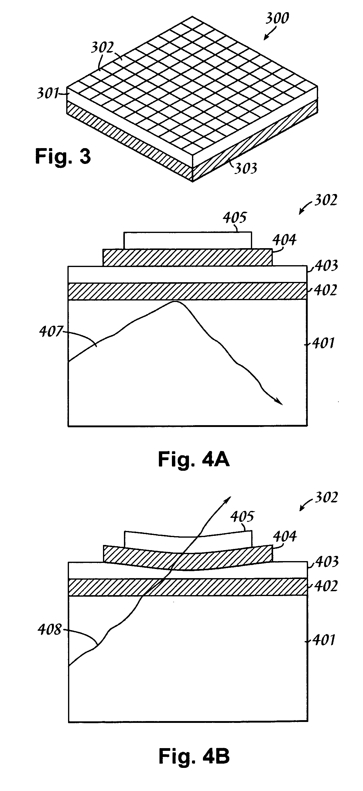
The interface between the cladding (stand-off system) and the waveguide may itself be subject to mild frustration of TIR because the refractive index of the cladding is greater than that of the refractive index of the air between the light sources and the waveguide insertion face, said mismatch meaning the critical angle for TIR is lower than expected at the display surface.
Further, this transparent material is interposed between the insertion face of the waveguide and the light source(s), such that the angular range of light admitted in the waveguide is sufficiently restricted to compensate for geometric errors in waveguide construction as well as for the fact that the cladding's refractive index is greater than that of air.

Method used


Image

  • Reducing light leakage and improving contrast ratio performance in FTIR display devices
  • Reducing light leakage and improving contrast ratio performance in FTIR display devices
  • Reducing light leakage and improving contrast ratio performance in FTIR display devices

Examples


Embodiment Construction

[0018] In the following description, numerous specific details are set forth to provide a thorough understanding of the present invention. However, it will be apparent to those skilled in the art that the present invention may be practiced without such specific details. In other instances, components have been shown in generalized form in order not to obscure the present invention in unnecessary detail. For the most part, details considering considerations of controlled selective dynamic frustration of total internal reflection (i.e., actual pixel operation) and the like have been omitted inasmuch as such details are not necessary to obtain a complete understanding of the present invention and, while within the skills of persons of ordinary skill in the relevant art, are not directly relevant to the utility and value provided by the present invention.

[0019] The principles of operation to be disclosed immediately below assume the presence of at least one of the two deleterious noise...


PUM


Abstract

An optical noise reduction mechanism for reducing undesired frustration of total internal reflected light. Such optical noise may stem from defects in waveguide construction. Such optical noise may also stem from the difference in refractive index between any cladding layers disposed onto the planar waveguide and the refractive index of the medium (e.g., air) between the light sources and the light insertion surface of the planar waveguide. By interposing a material of appropriate refractive index, either as a thin layer onto the light insertion surface of the waveguide or filling the space between the waveguide and the light source, the planar waveguide becomes more tolerant of geometry errors and cladding layer properties because a safe operating area is established between the unadjusted critical angle of the system and the actual range of ray angles allowed admittance into the waveguide.

Description

TECHNICAL FIELD [0001] The present invention relates in general to the field of flat panel displays, and more particularly to reducing the light leakage and improving contrast ratio performance in frustrated total internal reflection (FTIR) display devices. BACKGROUND INFORMATION [0002] Flat panel displays and other devices that exploit the principle of frustrated total internal reflection (FTIR) to induce the emission of light from the system may have to satisfy crucial physical criteria to function properly. The display system disclosed in U.S. Pat. No. 5,319,491, which is incorporated by reference in its entirety herein, as representative of a larger class of FTIR-based devices, illustrates the fundamental principles at play within an FTIR-based device. Such a device is able to selectively frustrate the light undergoing total internal reflection within a (generally) planar waveguide. When such frustration occurs, the region of frustration constitutes a pixel suited to external co...

Claims


Application Information

Patent Timeline
Patent Type & Authority Applications(United States)
IPC IPC(8): G02B6/10
CPCG02B6/0023
Inventor SELBREDE, MARTIN G.
Owner RAMBUS DELAWARE
Why Eureka
Try Eureka