Fluid treatment apparatus

a treatment apparatus and flue gas technology, applied in the direction of water/sewage treatment by oxidation, water/sewage treatment by electrochemical methods, manufacturing tools, etc., can solve the problems of insufficient apparatus to achieve corrosion resistance or improve fuel efficiency, and achieve the effect of preventing corrosion or the formation of scale and maximizing combustion efficiency

Active Publication Date: 2007-03-01
LEE SANG JIN
View PDF19 Cites 7 Cited by
  • Summary
  • Abstract
  • Description
  • Claims
  • Application Information

AI Technical Summary

Benefits of technology

[0008] An object of the present invention is to provide a fluid treatment apparatus including a disc-shaped electrodes made of metal generating an electromotive force of negative potential in a contacting course of fluid and a fluid pipeline and arranged in parallel in a direction perpendicular to a main flow direction of the fluid, thereby increasing a contact area between the electrodes and the fluid and thus preventing corrosion or the formation of scale and maximizing a combustion efficiency.

Problems solved by technology

Since the conventional lacks a means for smoothly guiding flow of other fluid or a means for increasing a contact area, the apparatus is not enough to obtain the resistance to the corrosion or the improvement of fuel efficiency.

Method used


Image

  • Fluid treatment apparatus
  • Fluid treatment apparatus
  • Fluid treatment apparatus

Examples


Embodiment Construction

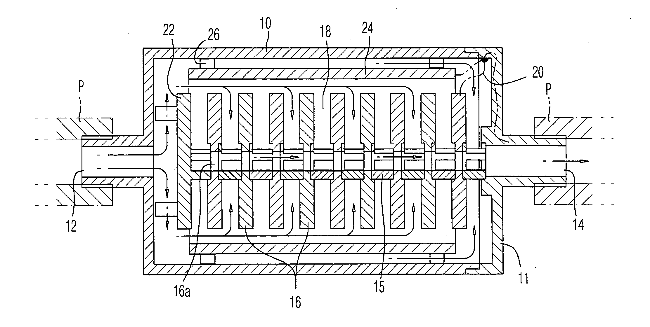
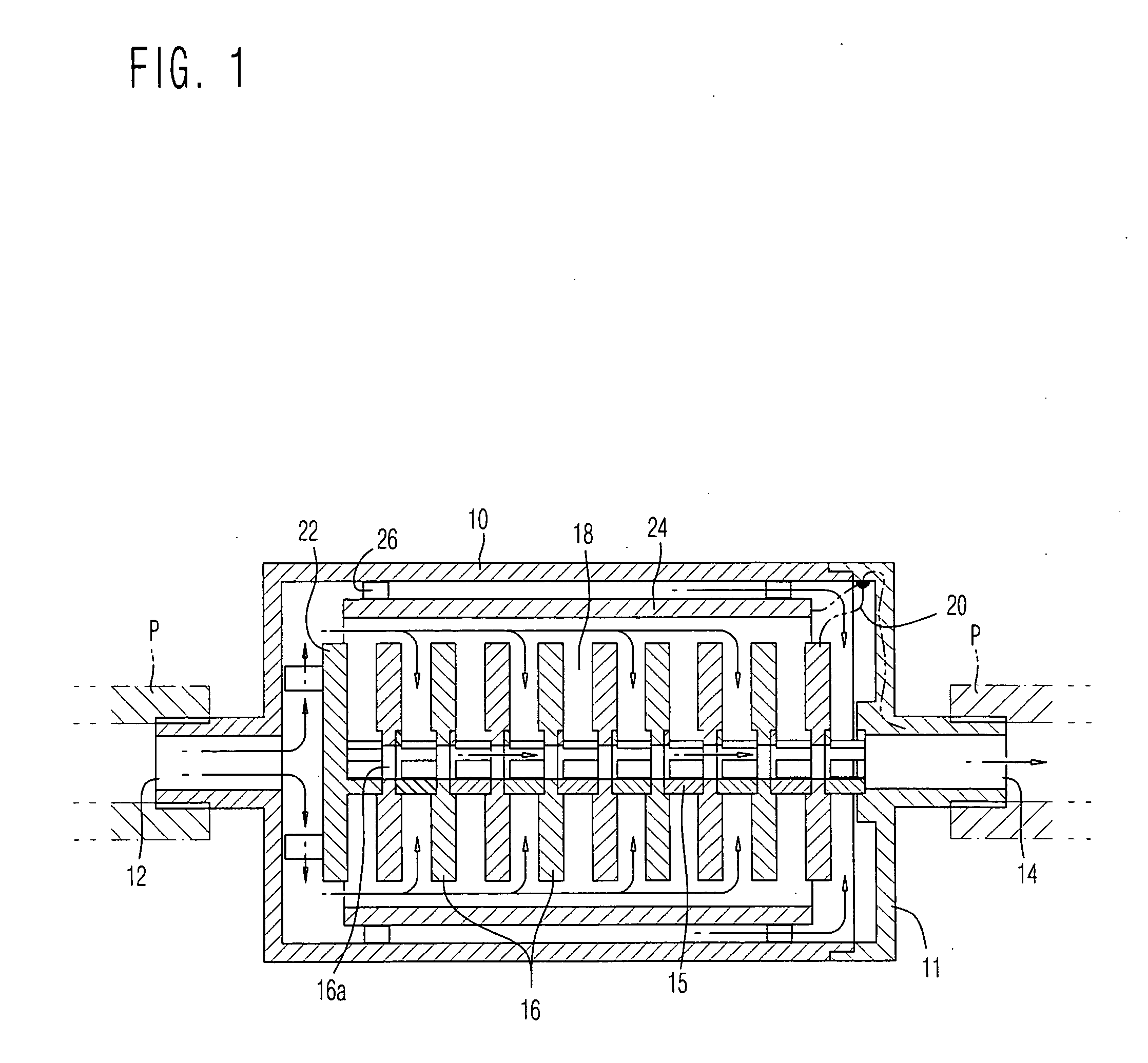
[0014] A preferred embodiment according to the present invention will now be explained with reference to the accompanying drawings.

[0015]FIG. 1 shows a fluid treatment apparatus according to the present invention in detail. The fluid treatment apparatus is installed in a fluid pipeline for feeding water or fuel for the purpose of converting the water into alkali ion water and generating hydrogen in the fuel, as well as preventing the corrosion of the inner wall of a pipe or the formation of scale on the inner wall, which can improve combustion efficiency. More particularly, the fluid treatment apparatus passes the fluid through an electrode made of a metal having an electromotive force and applies reduction potential, which is based on a potential difference generated at the contact portion between the fluid and the electrode, to the fluid, thereby reducing the forward reaction rate of various fluids such as water or fuel.

[0016] The fluid treatment apparatus is installed at a prop...


PUM

PropertyMeasurementUnit
pressureaaaaaaaaaa
electromotive forceaaaaaaaaaa
reduction potentialaaaaaaaaaa

Abstract

Disclosed is a fluid treatment apparatus capable of maximizing a contact area between a fluid and an electrode in the apparatus to improve a performance such as corrosion resistance and combustion efficiency The fluid treatment apparatus includes a housing having an inlet port and an outlet port for the water at both ends of the housing, and at least one first electrode installed in the housing for generating a potential difference through delivery of electrons at a contact surface between the fluid and the electrode, in which the first electrode is formed in a disc shape, and has a water passing hole formed in a center portion of the first electrode, and in which the first electrodes are arranged in parallel in a direction perpendicular to a main flow direction of the fluid, so as to form a channel between the first electrodes to branch and guide a main flow.

Description

BACKGROUND OF THE INVENTION [0001] 1. Field of the Invention [0002] The present invention relates to a fluid treatment apparatus capable of reducing the forward reaction rate of water or fuel in a fluid pipeline with use of the electromotive force of a metal, and more particularly, to a fluid treatment apparatus capable of maximizing a contact area between a fluid and an electrode in the apparatus to improve a performance such as corrosion resistance and combustion efficiency. [0003] 2. Background of the Related Art [0004] In general, fluid treatment apparatuses that reduce a fluid in a fluid pipeline to resist the corrosion of the pipeline or combustion efficiency of a fuel have been developed. Among the apparatuses, various devices employing so-called sacrificial anode method with use of a potential difference between a metal and a fluid (e.g., water or moisture contained in fuel) have been proposed. [0005] Such a fluid treatment apparatus can increase an amount of hydrogen in the...

Claims


Application Information

Patent Timeline
Patent Type & Authority Applications(United States)
IPC IPC(8): B01J19/08C02F1/46
CPCB01J19/088B01J2219/0813B01J2219/0815B01J2219/083B01J2219/0877B01J2219/0835B01J2219/0841B01J2219/0869B01J2219/0833
Inventor LEE, SANG JIN
Owner LEE SANG JIN
Why Eureka
Try Eureka