Methods for forming arrays of small, closely spaced features

Active Publication Date: 2007-03-01
MICRON TECH INC
View PDF71 Cites 345 Cited by
  • Summary
  • Abstract
  • Description
  • Claims
  • Application Information

AI Technical Summary

Benefits of technology

[0016] Some embodiments provide an array of features for computer memory fabrication. The array can have a middle tier comprising a grid with crossing lines, holes, and intersections, the lines having side walls. The array can also have a lower tier comprising a surface

Problems solved by technology

Because many photoresist materials respond selectively to particular wavelengths, photolithography techniques each have a minimum pitch below which that particular photolithographic technique cannot reliably form features.
Due to factors such as geometric complexity and different requirements for critical dimensions in different parts of an integrated circuit, typically not all features of the i

Method used


Image

  • Methods for forming arrays of small, closely spaced features
  • Methods for forming arrays of small, closely spaced features
  • Methods for forming arrays of small, closely spaced features

Examples


example

[0120]FIGS. 13 and 14 are scanning electron micrographs (SEMs) illustrating a dense array of small holes formed according to the described embodiments. These SEMs show structure that can be used to make holes having a pitch of approximately 200 nm by 250 nm. The features shown have a width of approximately 95 nm in the critical dimension.

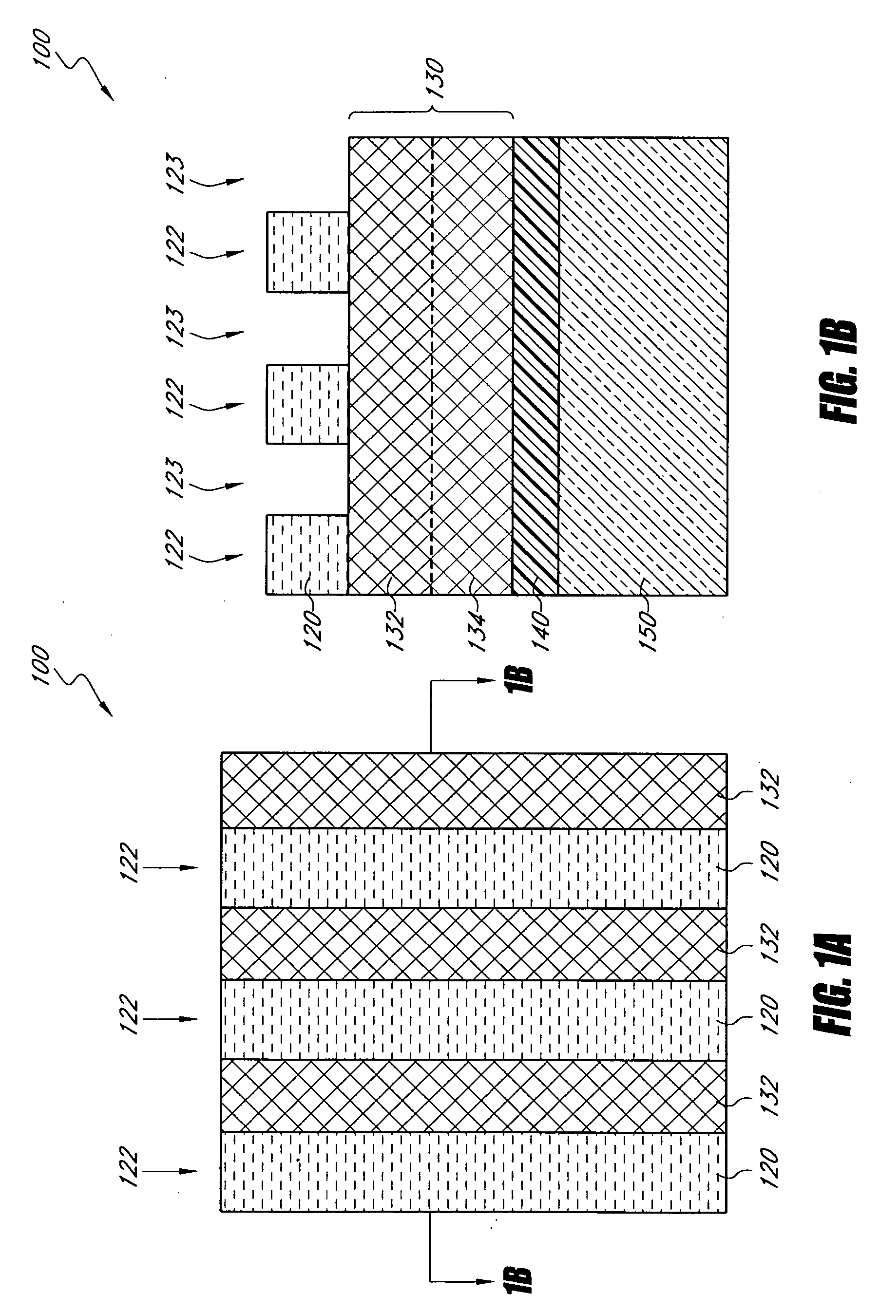
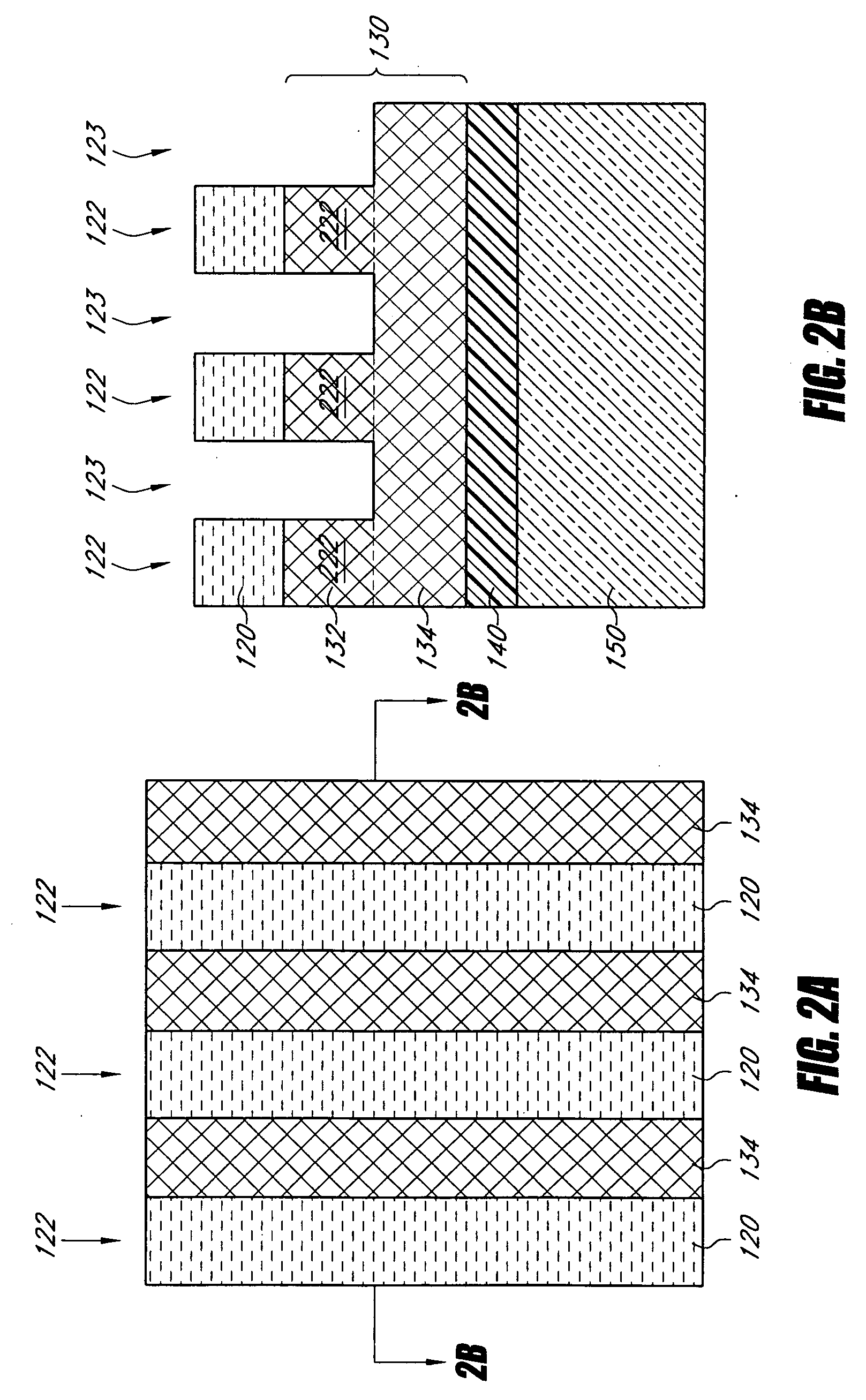
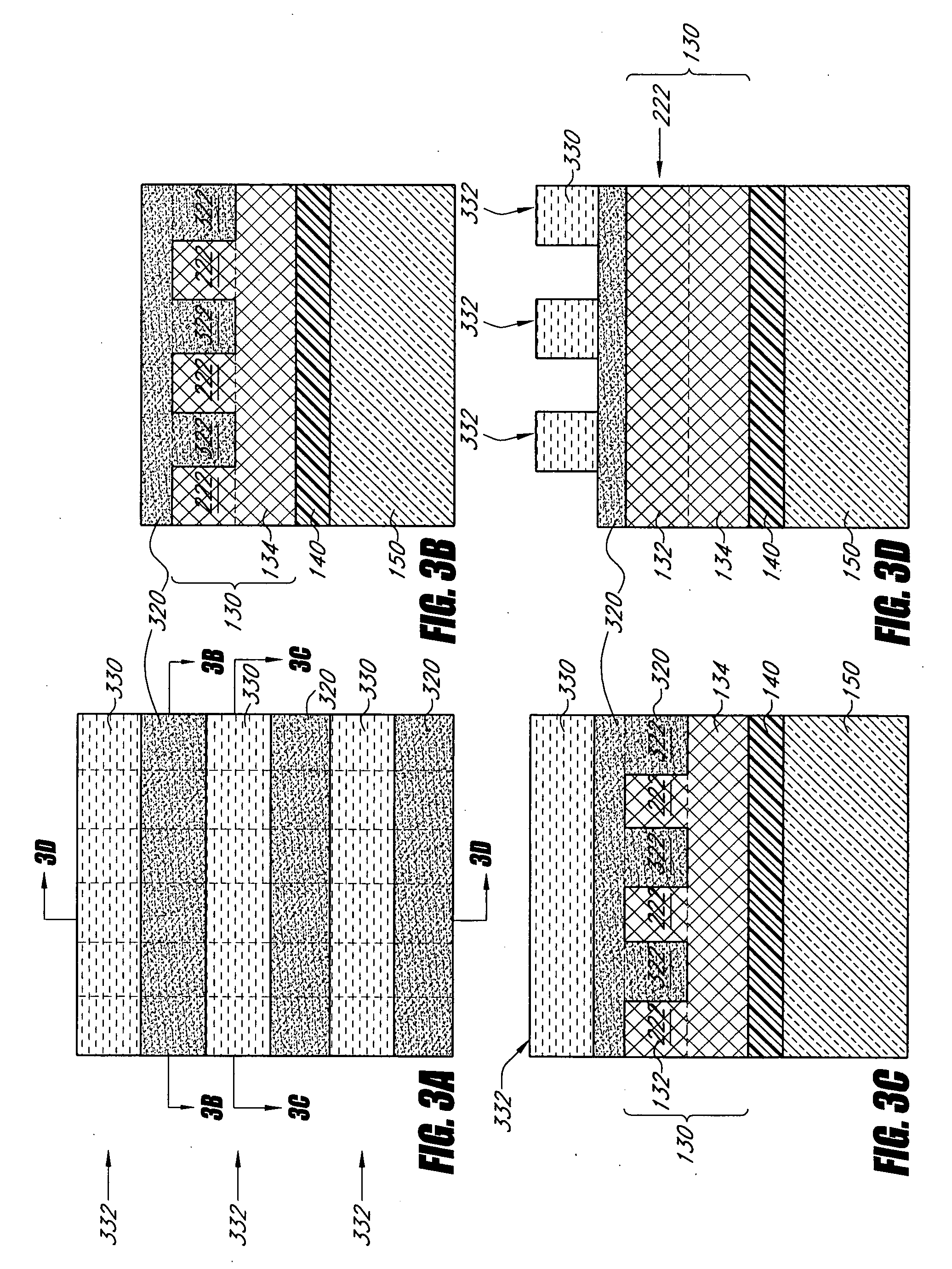
[0121] To achieve the structure shown, the process described in FIGS. 1-6 was generally followed, with the exception that an extra layer of DARC was used above the temporary layer 130. The extra DARC layer was approximately 1200 angstroms (A) thick. The half-etch process resulting in multiple exposed layers (depicted in FIG. 6E, for example) was accomplished in the DARC layer and then transferred into the underlying temporary layer 130 (which was formed from transparent carbon (TC) in this example). In FIG. 13, the DARC layer has been removed after the pattern was extended into the TC layer. In this example, the TC is approximately 3,000 Å thick an...


PUM


Abstract

Methods of forming arrays of small, densely spaced holes or pillars for use in integrated circuits are disclosed. Various pattern transfer and etching steps can be used, in combination with pitch-reduction techniques, to create densely-packed features. Conventional photolithography steps can be used in combination with pitch-reduction techniques to form superimposed patterns of crossing elongate features with pillars at the intersections. Spacers are simultaneously applied to sidewalls of both sets of crossing lines to produce a pitch-doubled grid pattern. The pillars facilitate rows of spacers bridging columns of spacers.

Description

REFERENCE TO RELATED APPLICATIONS [0001] This application is related to the following: U.S. patent application Ser. No. ______ (MICRON.313A) filed Aug. 31, 2005; U.S. patent application Ser. No. 11 / 134,982 (MICRON.317A) filed May 23, 2005; and U.S. patent application. Ser. No. ______ (MICRON.330A) filed on even date herewith. Each of the above-mentioned references is hereby incorporated by reference in its entirety and made part of this specification.BACKGROUND OF THE INVENTIONS [0002] 1. Field of the Inventions [0003] The disclosed invention relates generally to integrated circuit fabrication, techniques for fabrication of computer memory, and masking techniques. [0004] 2. Description of the Related Art [0005] As a consequence of many factors, including demand for increased portability, computing power, memory capacity and energy efficiency in modern electronics, integrated circuits are continuously being reduced in size. To facilitate this size reduction, research continues into w...

Claims


Application Information

Patent Timeline
IPC IPC(8): G03F7/26
CPCH01L27/101H01L27/1021H01L27/112H01L27/11206H01L27/115H01L21/76885H01L45/085H01L45/144H01L45/1683H01L27/1052H01L21/76802H01L45/06H01L21/0337H01L21/31122H01L21/31138H01L21/31144H01L21/76816H10N70/245H10N70/231H10N70/8828H10N70/066H10B99/00H10B20/00H10B20/20H10B69/00H10N70/068H10N70/021H10N70/8265H10N70/8845
Inventor WELLS, DAVID H.
Owner MICRON TECH INC
Why Eureka
Try Eureka