Thermally enhanced piezoelectric element

a piezoelectric element and piezoelectric technology, applied in piezoelectric/electrostrictive device details, mechanical vibration separation, therapy, etc., can solve the problems of affecting the performance of the transducer, generating unwanted heat, and unwanted hea

Inactive Publication Date: 2007-03-01
UST INC
View PDF4 Cites 34 Cited by
  • Summary
  • Abstract
  • Description
  • Claims
  • Application Information

AI Technical Summary

Problems solved by technology

Conventional ultrasound transducers used for medical applications, such as High Intensity Focused Ultrasound (HIFU), generate unwanted heat that can affect performance of the transducer.
This unwanted heat is due to piezoelectric elements, used therein, having some inefficiency in converting electrical power into acoustic waves.
Ceramic piezoelectric elements typically have low thermal conductivity (such as approximately one to two W/mC), which contributes in part to the unwanted heat producing undesirable elevated temperatures.
If a transducer does not come into contact with a patient, generally higher temperatures are permitted, however, temperature levels in excess of 80 or 90 degrees centigrade are most likely to result in damage to the transducer and/or portions of electrical and/or mechanical eleme

Method used


Image

  • Thermally enhanced piezoelectric element
  • Thermally enhanced piezoelectric element
  • Thermally enhanced piezoelectric element

Examples


Embodiment Construction

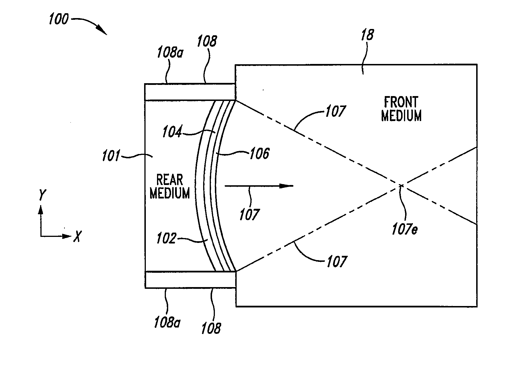
[0054] A system and method for removing unwanted heat generated by a piezoelectric element of an ultrasound transducer while maintaining transducer efficiencies is disclosed herein. In some implementations, relatively small amounts of high thermal conductivity (HTC) material are placed in juxtaposition with the piezoelectric element on front and / or back surfaces of the piezoelectric element. Generally HTC materials have a thermal conductivity of over 100 W / mC. Some HTC materials can include metals and other materials of high thermal conductivity (for instance, aluminum at approximately 205-237 W / mC, copper at approximately 385-401 W / mC, gold at approximately 314-318 W / mC, silver at 406-429 W / mC, brass at approximately 109-159 W / mC, impure diamond at approximately 1,000 W / mC, and purified synthetic diamond at approximately 2,000-2,500 W / mC thermal conductivity).

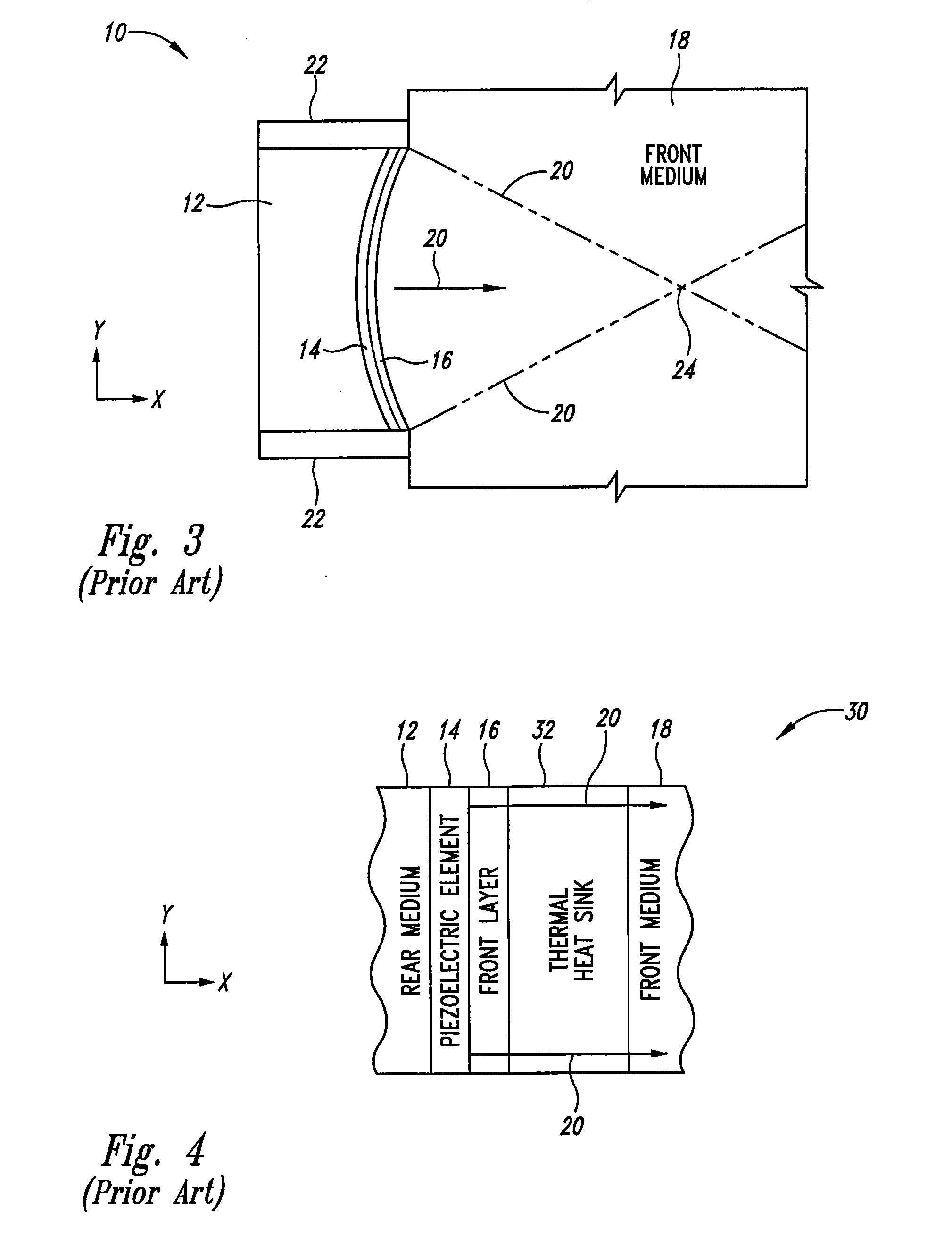
[0055] The HTC material can be thermally coupled to one or more heat sinks, which can be integrated with the ultrasound tra...


PUM


Abstract

A system and method for removing unwanted heat generated by a piezoelectric element of an ultrasound transducer. Some implementations have high thermal conductivity (HTC) material placed adjacent to the piezoelectric element. The HTC material can be thermally coupled to one or more heat sinks. Use of HTC material in conjunction with these piezoelectric element surfaces is managed to avoid degradation of propagating acoustic energy. Use of the HTC material in conjunction with heat sinks allows for creation of thermal paths away from the piezoelectric element. Active cooling of the heat sinks with water or air can further draw heat from the piezoelectric element. Further implementations form a composite matrix of thermally conductive material or interleave thermally conductive layers with piezoelectric material.

Description

CROSS REFERENCE TO RELATED APPLICATION [0001] This application claims priority benefit of provisional application Ser. No. 60 / 700,772 filed Jul. 20, 2005.BACKGROUND OF THE INVENTION [0002] 1. Field of the Invention [0003] The present invention is directed to ultrasound transducers for medical applications. [0004] 2. Description of the Related Art [0005] Conventional ultrasound transducers used for medical applications, such as High Intensity Focused Ultrasound (HIFU), generate unwanted heat that can affect performance of the transducer. This unwanted heat is due to piezoelectric elements, used therein, having some inefficiency in converting electrical power into acoustic waves. Ceramic piezoelectric elements typically have low thermal conductivity (such as approximately one to two W / mC), which contributes in part to the unwanted heat producing undesirable elevated temperatures. [0006] Some medical and other applications require transducer temperatures to be kept in narrow ranges. Fo...

Claims


Application Information

Patent Timeline
IPC IPC(8): A61B8/14
CPCA61N7/02H01L41/083H01L41/04B06B1/0677H10N30/80H10N30/50
Inventor KAMINSKI, PERRYCHU, YU-CHI
Owner UST INC
Why Eureka
Try Eureka