Compression device for the limb

a compression device and limb technology, applied in the field of compression devices for the limbs, can solve the problems of insufficient use of the device, failure to follow the compression therapy schedule prescribed by a healthcare professional, and longer healing time for the patient, and achieve the effect of low profile, greatest effect on blood flow, and low profil

Active Publication Date: 2007-03-01
SWELLING SOLUTIONS
View PDF10 Cites 94 Cited by
  • Summary
  • Abstract
  • Description
  • Claims
  • Application Information

AI Technical Summary

Benefits of technology

[0023] Preferably, the sleeve is low profile and discrete, allowing the patient to use the device while wearing ordinary clothes and shoes.
[0024] Preferably, the sleeve comprises a leg cuff and a foot cuff both of which are low profile and discrete. Preferably, the leg and foot cuffs are anatomically shaped to provide compression on those parts of the leg or foot which have the greatest effect on blood flow. This provides the advantage of reducing the overall size of the device and, thus, the profile of the cuff and size and power of the pump. Depending on the shape of the cuffs, it can also reduce discomfort from pressure on bony areas of the limb.

Problems solved by technology

However, as with all of the previously referenced devices, compliance with treatment can be a problem as a patient treated at home or in the community may remove the device, for any of the reasons mentioned, which can result in insufficient usage of the device and failure to follow a compression therapy schedule prescribed by a healthcare professional.
This can lead to a longer healing time for the patient.

Method used


Image

  • Compression device for the limb
  • Compression device for the limb
  • Compression device for the limb

Examples


Embodiment Construction

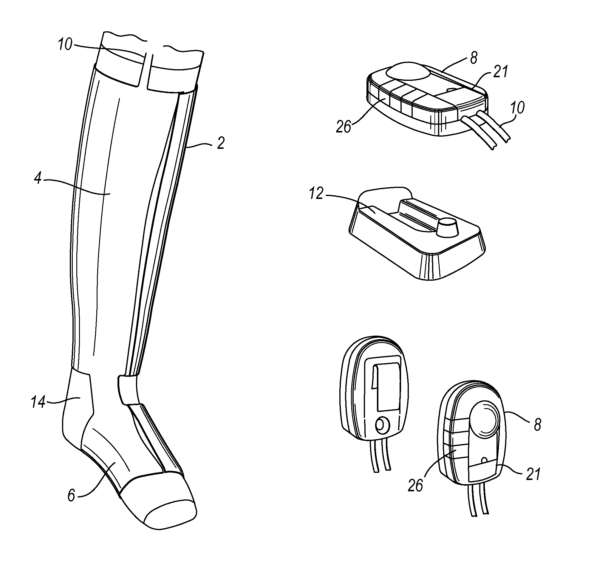
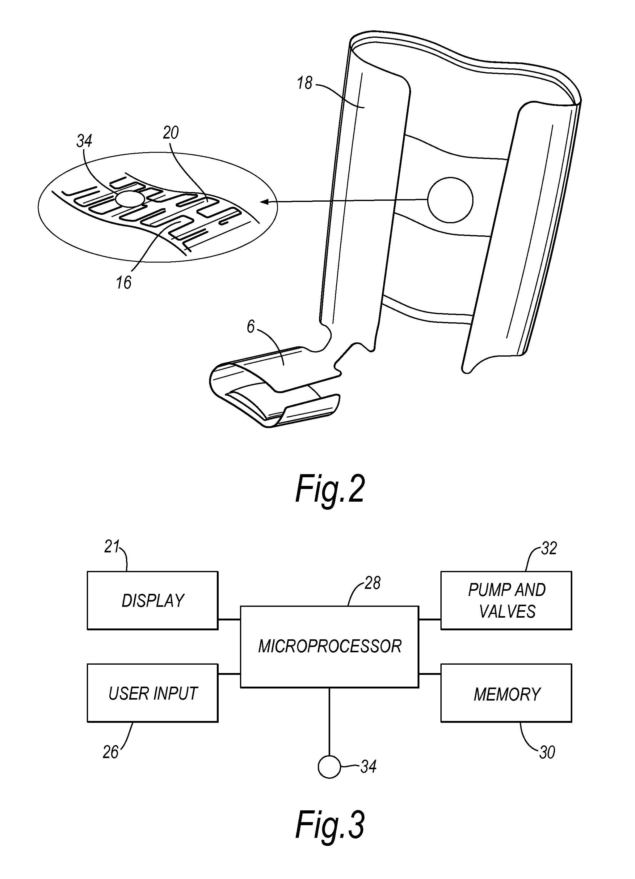
[0032] In FIG. 1 the compression device of the invention is shown on the leg of a patient in a standing position. The compression device comprises a sleeve 2 having a leg cuff 4 connected to a foot cuff 6. The compression device also comprises a control system housed within a controller unit 8. The sleeve 2 is connected to the controller unit 8 by a conduit 10. The controller unit 8 is a small, hand held unit that may be clipped to the sleeve 2 or to the waistband of the patient's trousers or skirt. The controller unit 8 is battery powered, e.g., by a Lithium battery, and rechargeable so that it can be recharged on a base unit 12. The compression device also comprises an understocking 14 worn between the patient's leg and the sleeve 2. The understocking 14 is present to absorb any moisture from the patient's leg but is not intended to apply compression. The sleeve 2 has an inner surface 16 and an outer surface 18 composed of a durable flexible material that can be sponged clean and ...


PUM


Abstract

A compression device for a limb of a patient comprises an inflatable sleeve arranged to surround the limb and a conduit attached to the sleeve arranged to deliver fluid to the sleeve. The compression device also comprises a control system arranged to control fluid flow in the device and a memory arranged to store gathered data relating to use of the device.

Description

[0001] This invention relates to a compression device for the limb and particularly to a device for use on the leg. For example, the device may be used for compression therapy used in the treatment of venous leg ulcers. BACKGROUND OF THE INVENTION [0002] Various compression devices are known for applying compressive pressure to a patient's limb. These types of devices are used to assist mainly in the prevention of deep vein thrombosis (DVT), vascular disorders and the reduction of oedema. U.S. Patent Application No. 2004 / 0111 048 (Jensen, et al.) and U.S. Pat. No. 6,786,879 (KCI Licensing Inc.) disclose such devices. [0003] Compression therapy is used in the treatment of venous leg ulcers. The treatment relies on the compression achieving a reduction in oedema and improved return of blood via the venous system. This, in turn, reduces the residence time for blood supplied to the lower limb and the severity of ischaemic episodes within the limb that can result in tissue breakdown. [00...

Claims


Application Information

Patent Timeline
Patent Type & Authority Applications(United States)
IPC IPC(8): A61H9/00A61H23/04
CPCA61H9/0078Y10S601/20A61H2205/10
Inventor ADAMS, SIMON MARKFERNANDEZ, JOSE ARSENIOCHRISTIANSSON, MATSBONNEFIN, WAYNE LEEWILD, DAVID GEOFFREY
Owner SWELLING SOLUTIONS
Why Eureka
Try Eureka