
Impulse chamber for jet delivery device

Inactive Publication Date: 2007-03-01
NOVO NORDISK AS +1
View PDF23 Cites 9 Cited by
  • Summary
  • Abstract
  • Description
  • Claims
  • Application Information

AI Technical Summary

Benefits of technology

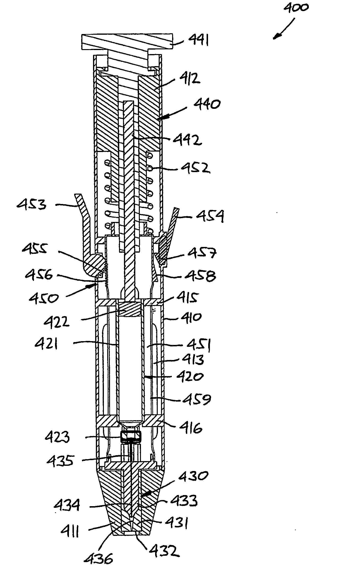
[0017] As appears, by this arrangement only the piston will have to be moved relative to the reservoir and the nozzle during filling respectively emptying of the impulse chamber, this allowing for a compact and simple design. By this design a very compact chamber unit can be provided in which the fluid communication can be integrated with the volume-varying structures.
[0021] To prevent excessive back-flow of fluid from the impulse chamber during actuation of the piston to empty the impulse chamber, the fluid inlet may comprise a uni-directional inlet valve, a narrow flow restriction or a tortuous path portion. However, the fluid inlet may be “open” to allow an amount of drug to be forced backwardly into the reservoir during expelling of drug from the impulse chamber, the flow resistance of the outlet nozzle, the flow resistance of the fluid inlet and the impulse generating assembly being configured to allow a backflow of less than 15%, preferably less than 10%, more preferably less than 5% and most preferably less than 1%.
[0025] When initially an opening has been created in the skin, a lower force can be used to inject a remaining drug dose through the opening for which reason the jet expelling device may further comprise drive means for reducing the volume of the impulse chamber with a reduced force relative to the impulse generating means when the latter has been actuated.
[0035] In a yet further aspect a jet injection assembly is provided comprising an impulse chamber unit as described above, in combination with a jet injection device and a reservoir mounted relative thereto, wherein the reservoir is adapted to contain (or contains) a liquid drug and comprises an outlet allowing the fluid inlet to be arranged in fluid communication with an interior of the reservoir, the jet injection device comprising means for expelling an amount of drug from the reservoir to the impulse chamber via the fluid inlet thereby expanding the impulse chamber. To expel an amount of drug through the outlet nozzle the jet injection device comprises impulse generating means for reducing the volume of the impulse chamber.

Problems solved by technology

Many patients dislike needle injections due to pain or fear for needles.
This disposal presents a problem to individuals other than healthcare workers.
Children, for example, may find used needles in the trash, putting them at risk of contracting infection.
Discarded needles likewise pose a risk to waste disposal workers.
Transferring the fluid drug adds cost to administering injections in a hospital or clinic because of the labor expense.
Immunizing large populations requires administering many injections per hour, hence transferring the fluid drug presents a significant time constraint.
For the patient who must self-administer fluid drugs, such as a diabetic patient requiring several insulin injections a day, transferring the fluid drug can be an inconvenience.
Also, with each transfer, there is an opportunity for error in the amount of fluid drug being transferred and administered.
A disadvantage of pre-filled cartridges, however, is that they still require using a needle to penetrate the skin and deliver the medication to the target tissue.
Neither glass vials containing multiple doses of a drug nor pre-filled cartridges can be used with traditional jet injectors.
For example, if the force generated by the jet injector drive means was applied directly to the piston the cartridge would in most cases burst.
Although not directly impacted, the glass walls of the cartridge do not have sufficient strength to withstand the large amplitude pressure waves that result when the ram impacts the piston.

Method used


Image

  • Impulse chamber for jet delivery device
  • Impulse chamber for jet delivery device
  • Impulse chamber for jet delivery device

Examples


Embodiment Construction

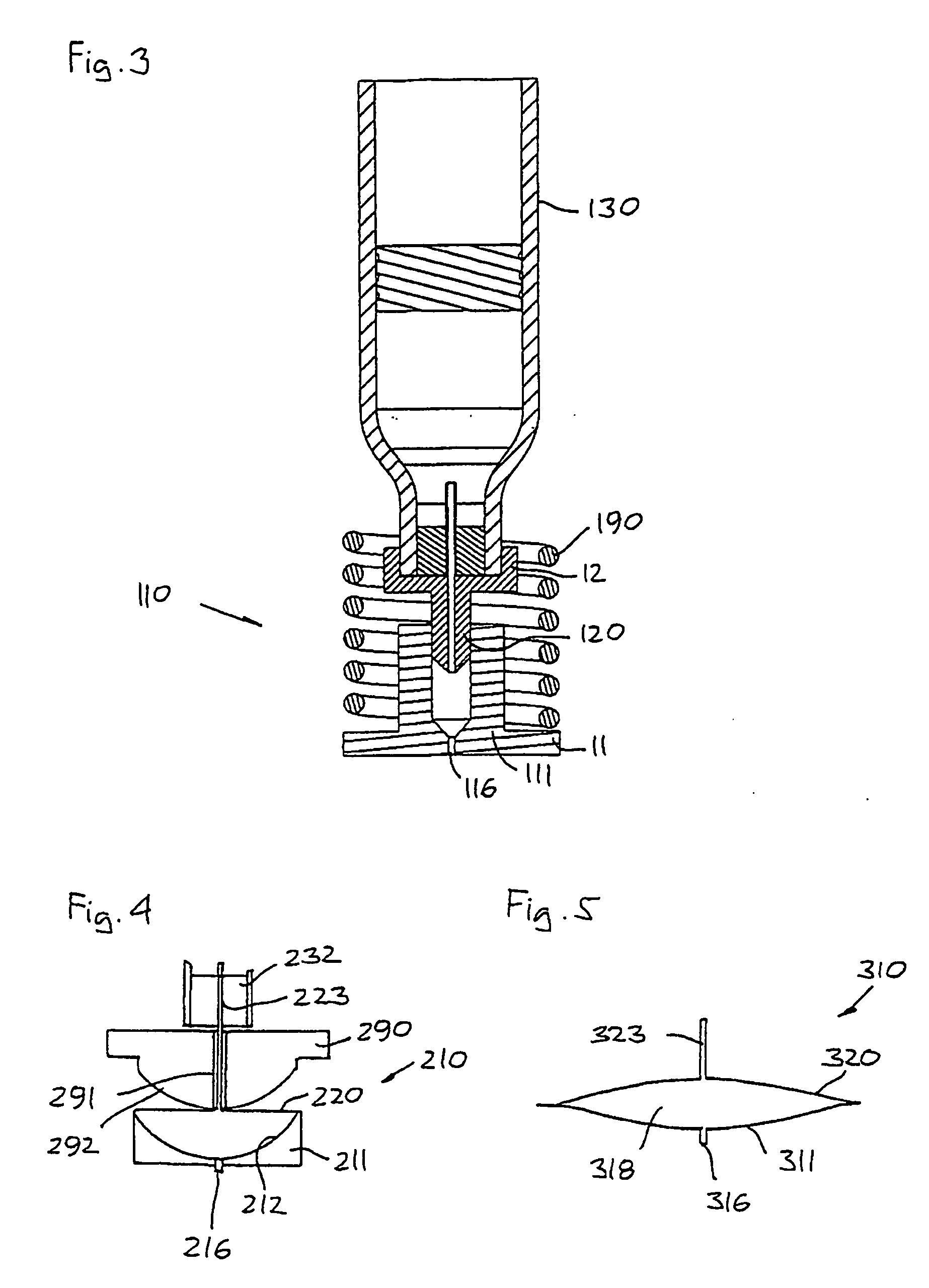
[0048] When in the following terms as “upper” and “lower”, “right” and “left”, “horizontal” and “vertical” or similar relative expressions are used, these only refer to the appended figures and not to an actual situation of use. The shown figures are schematic representations for which reason the configuration of the different structures as well as there relative dimensions are intended to serve illustrative purposes only.

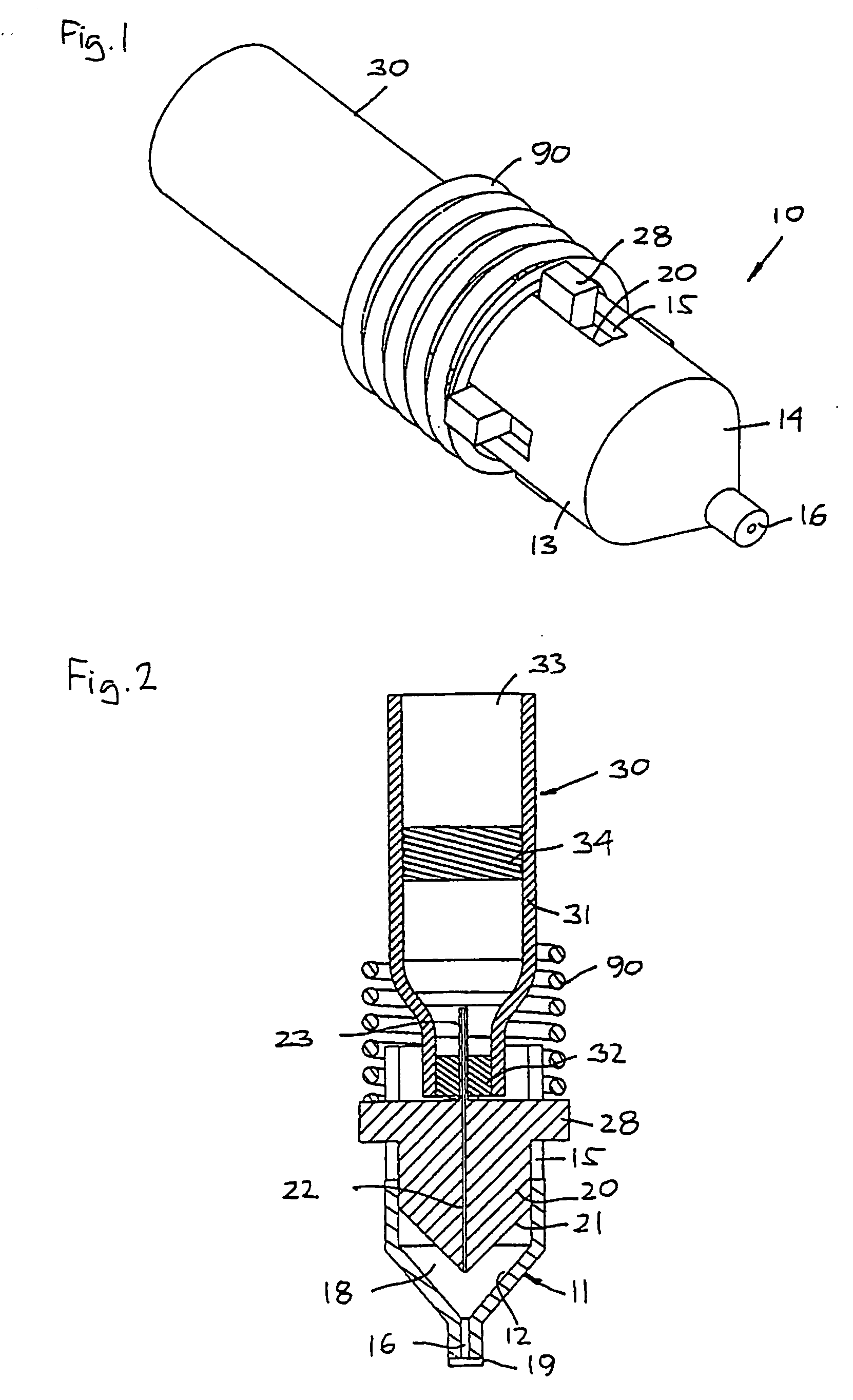
[0049]FIG. 1 shows a perspective view of an impulse chamber unit 10 in combination with a drug cartridge 30 and a coil spring 90, the latter representing a portion of impulse generating means (not shown in full).

[0050] Turning to FIG. 2, the impulse chamber unit 10 comprises a housing member 11 defining an interior cavity 12, the housing having a generally cylindrical main portion 13 with a conical distal end portion 14 and a proximal opening. A number of longitudinal slots 15 are formed in the proximal portion of the housing, the slots extending to the proximal ...


PUM


Abstract

The invention provides a jet expelling assembly comprising a reservoir and an impulse chamber assembly. The impulse chamber assembly comprises a chamber portion defining a cavity having a general axis, a piston received in the cavity along the general axis and comprising a fluid inlet, thereby defining a variable-volume impulse chamber with an outlet nozzle. The inlet comprises a conduit adapted to slidably engage a reservoir outlet during relative movement therebetween. The chamber portion is arranged stationary relative to the reservoir, whereby expelling an amount of drug from the reservoir to the impulse chamber via the inlet causes the piston to move towards the reservoir, the impulse chamber thereby receiving the expelled amount of drug.

Description

CROSS-REFERENCE TO RELATED APPLICATIONS [0001] This application is a continuation of International Application Number: PCT / DK2004 / 000817, filed Nov. 25, 2004, which claims priority to Danish Patent Application Number PA 2003 01751, filed Nov. 27, 2003, and U.S. Provisional Application No. 60 / 526,829, filed Dec. 4, 2003, the contents of each of which is incorporated herein in its entirety. [0002] The invention relates to an impulse chamber which can be used for expelling an amount of a fluid compound from a reservoir at a high pressure. The impulse chamber may be used e.g. in a skin-penetrating jet injection device or it may be used as a nebulizing means in an inhalation device e.g. for pulmonary administration of a drug. BACKGROUND OF THE INVENTION [0003] Subcutaneous and intramuscular delivery of liquid drugs by injection is common in the medical arts. As some medications, such as insulin, must be given frequently by injection to an individual, it is desirable that the injections c...

Claims


Application Information

Patent Timeline
IPC IPC(8): A61M5/30A61M5/20A61M5/24A61M5/31
CPCA61M5/204A61M5/24A61M5/282A61M2005/3128A61M5/30A61M5/20
Inventor HANSEN, TORBEN STROM
Owner NOVO NORDISK AS
Learn More