Impulse chamber for jet delivery device

a jet and impulse technology, applied in the direction of intravenous devices, medical syringes, infusion syringes, etc., can solve the problems of needle injection, disposal presents a problem to individuals other than healthcare workers, and puts them at risk of infection, and achieves the effect of convenient us

Inactive Publication Date: 2007-03-01
NOVO NORDISK AS
View PDF14 Cites 340 Cited by
  • Summary
  • Abstract
  • Description
  • Claims
  • Application Information

AI Technical Summary

Benefits of technology

[0018] Correspondingly, in a first aspect an impulse chamber unit is provided comprising a deformable chamber portion, the outer surface of the chamber portion being substantially free, a variable-volume impulse chamber defined at least partially by the deformable chamber portion and adapted for containing a volume of a flowable drug, an outlet nozzle in fluid communication with the impulse chamber and being adapted to be arranged against a skin surface of a subject, and a fluid inlet for the impulse chamber, wherein deformation of the chamber portion reduces the volume of the impulse chamber. In a preferred embodiment the variable-volume impulse chamber is defined substantially by the deformable chamber portion.
[0021] As elastomeric materials such as silicone rubber typically are almost incompressible, deformation of the tube under well-defined, enveloped conditions can with simple measures reliably provide high precision skin penetrating jets. Further, a rubber tube is simple and cost-efficient to manufacture and takes up little space during transportation. Also, a rubber tube is robust with relation to impacts occurring during use and transportation.
[0022] By varying the dimensions and the configuration of the impulse chamber it is possible to vary the characteristics of the jet under unchanged conditions for the surrounding structures. For example, for a given outer tube diameter the inner diameter may be varied, this resulting in jet injections of different volumes without having to necessarily modify the impact or mounting means.
[0032] Advantageously, the impulse generating means comprises a piston adapted for deforming the chamber portion, a rotatable cam for moving the piston and a drive mechanism for rotating the cam. In a preferred embodiment the cam is rotated by means of a torsion spring, this allowing the user to directly strain the spring by a rotational action. This type of actuation is advantageous as it resembles the dose setting means used in most injection devices of the pen type, thus also allowing the spring actuation and the dose setting to be coupled to each other in a simple and reliable manner.

Problems solved by technology

Many patients dislike needle injections due to pain or fear for needles.
This disposal presents a problem to individuals other than healthcare workers.
Children, for example, may find used needles in the trash, putting them at risk of contracting infection.
Discarded needles likewise pose a risk to waste disposal workers.
Such jet injectors are typically large as compared to needle injectors, e.g. pen type needle injectors, which of course is a disadvantage in relation to handling and transportation.
Further the size and shape of such apparatuses can have an intimidating effect on many patients.
Thus, when the derma has been penetrated and the jet enters the fragile subcutaneous tissue, the pressure of the liquid jet is still high, possibly causing lesions to the subcutaneous tissue, e.g. damaging tissue cells, nerve fibres and fine blood vessels.
This may cause haemorrhage and pain and trauma for the patient.
Further the damage to the tissue can trigger an immune reaction in the tissue, causing the chemical environment at the injection site to change.
This can influence the effect of the injected substance, which of course is highly undesirable.
This tissue has a lot of blood vessels and will absorb the insulin too quickly, with the risk of resulting in insulin chock.
The driving mechanisms of these devices all have rather complicated structures because they need to be able to deliver two distinct bursts of force.
Whenever a medical device comes in contact with e.g. the skin of a patient or is handled there is a risk of contamination of the device.

Method used


Image

  • Impulse chamber for jet delivery device
  • Impulse chamber for jet delivery device
  • Impulse chamber for jet delivery device

Examples


Embodiment Construction

[0044] When in the following terms as “upper” and “lower”, “right” and “left”, “horizontal” and “vertical” or similar relative expressions are used, these only refer to the appended figures and not to an actual situation of use. The shown figures are schematic representations for which reason the configuration of the different structures as well as there relative dimensions are intended to serve illustrative purposes only.

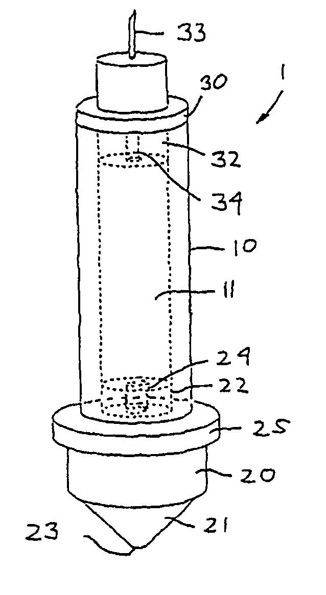
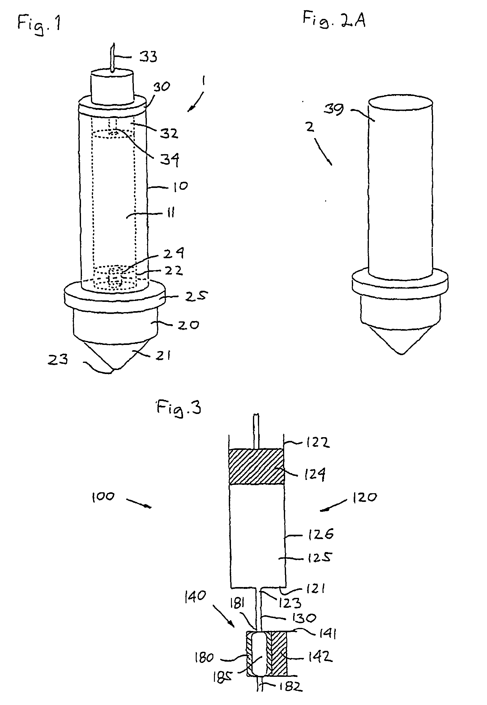
[0045]FIG. 1 shows a perspective view of an impulse chamber unit 1 comprising a deformable chamber portion in the form of an elastomeric tube member 10, a distal nozzle portion closure member 20 and a proximal fluid inlet closure member 30. The unit comprises a tubular variable-volume impulse chamber 11 adapted for containing a volume of a flowable drug, the impulse chamber being defined substantially by the tube member, the two closure members merely providing the end portions of the impulse chamber. Alternatively the closure members may comprise extensions makin...


PUM


Abstract

The invention relates to an impulse chamber which can be used for expelling an amount of a fluid compound at a high pressure. The impulse chamber comprises a variable-volume impulse chamber adapted for containing a volume of a flowable drug, an outlet nozzle in fluid communication with the impulse chamber and being adapted to be arranged against the skin of a subject, and a fluid inlet in fluid communication with the impulse chamber. The impulse chamber is defined substantially by a deformable chamber portion, such that deformation thereof reduces the volume of the cavity. In an exemplary embodiment the compressible chamber portion is in the form of an elastomeric tube, this providing a simple, yet reliable and cost-effective impulse chamber unit.

Description

BACKGROUND OF THE INVENTION [0001] Subcutaneous and intramuscular delivery of liquid drugs by injection is common in the medical arts. As some medications, such as insulin, must be given frequently by injection to an individual, it is desirable that the injections can be performed easily. [0002] Many patients dislike needle injections due to pain or fear for needles. Further, blood-borne pathogens, such as HIV and hepatitis, can be transmitted to health care workers by accidental needle-sticks. Also, the disposal of used needles is a growing concern. This disposal presents a problem to individuals other than healthcare workers. Children, for example, may find used needles in the trash, putting them at risk of contracting infection. Discarded needles likewise pose a risk to waste disposal workers. [0003] In efforts to minimize the fears and risks associated with needle injections, several types of needle-free jet injectors have been developed. These devices make the drug penetrate th...

Claims


Application Information

Patent Timeline
Patent Type & Authority Applications(United States)
IPC IPC(8): A61M5/00A61M5/24A61M5/30A61M5/48
CPCA61M5/2425A61M5/482A61M5/30
Inventor HANSEN, TORBENMOLLER, CLAUS
Owner NOVO NORDISK AS
Why Eureka
Try Eureka