Lumen-supporting stents and methods for creating lumen-supporting stents with various open/closed designs

Inactive Publication Date: 2007-03-01
MEDLOGICS DEVICE CORP
View PDF15 Cites 52 Cited by
  • Summary
  • Abstract
  • Description
  • Claims
  • Application Information

AI Technical Summary

Benefits of technology

[0008] One design of the present invention is an “open-closed-open” design. This design provides for greater flexibility at both ends of the stent. This feature can provide for a less abrupt transition between stented and unstented portions of a vessel and can also improve the deliverability of the stent.
[0009] A second design of the stents of the present invention includes a “closed-open-closed” design. This stent design can be beneficial when the area to be treated is in the vicinity of (i.e. found before and after) a vessel branch or bifurcation. The open middle portion of the stent provides for greater flexibility so that the stent can conform more readily to the irregular shape of this portion of the vessel. In addition, when treating a vessel in an area of a vessel branch or bifurcation, it is common for the stent to pass over the opening to the second vessel, thereby impeding blood flow into the second vessel (i.e. “gating” the vessel). A more open middle portion can reduce this “gating” effect and allow for better blood flow into the second vessel. Further, if needed, the nature of an open middle portion allows another stent to be deployed through the open middle portion into a gated vessel branch. Closed ends around the open middle portion provide better and more uniform support on each side of the vessel bifurcation.
[0010] A third design of the stents of the present invention, the “closed-open” design include stents that are closed

Problems solved by technology

Unfortunately, while the affected vessel can be enlarged thus improving blood flow, in some instances the vessel re-occludes chronically (“restenosis”), or closes down acutely (“abrupt reclosure”), negating the positive effect of the angioplasty procedure.
While such reste

Method used


Image

  • Lumen-supporting stents and methods for creating lumen-supporting stents with various open/closed designs
  • Lumen-supporting stents and methods for creating lumen-supporting stents with various open/closed designs
  • Lumen-supporting stents and methods for creating lumen-supporting stents with various open/closed designs

Examples


Example

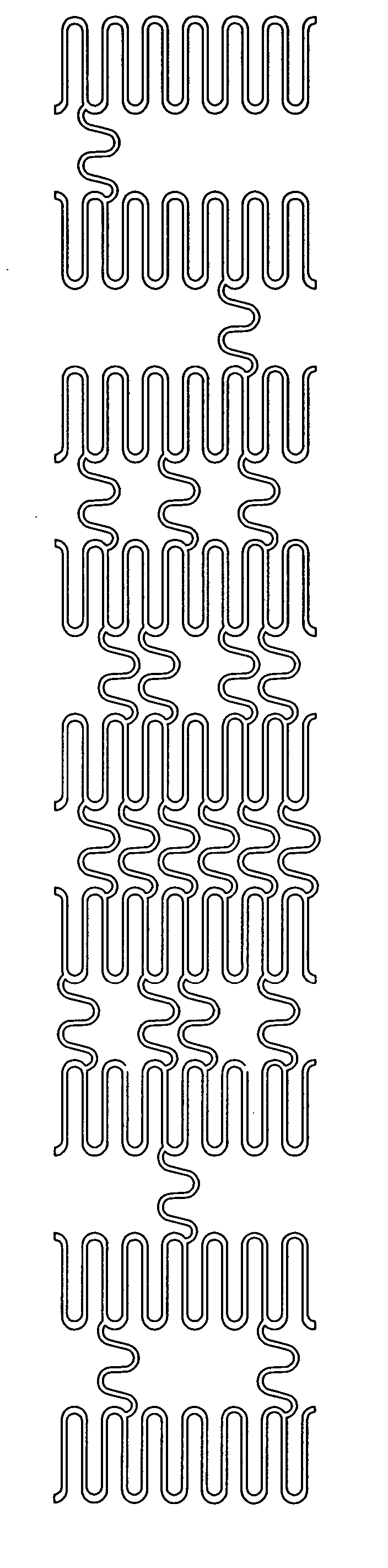
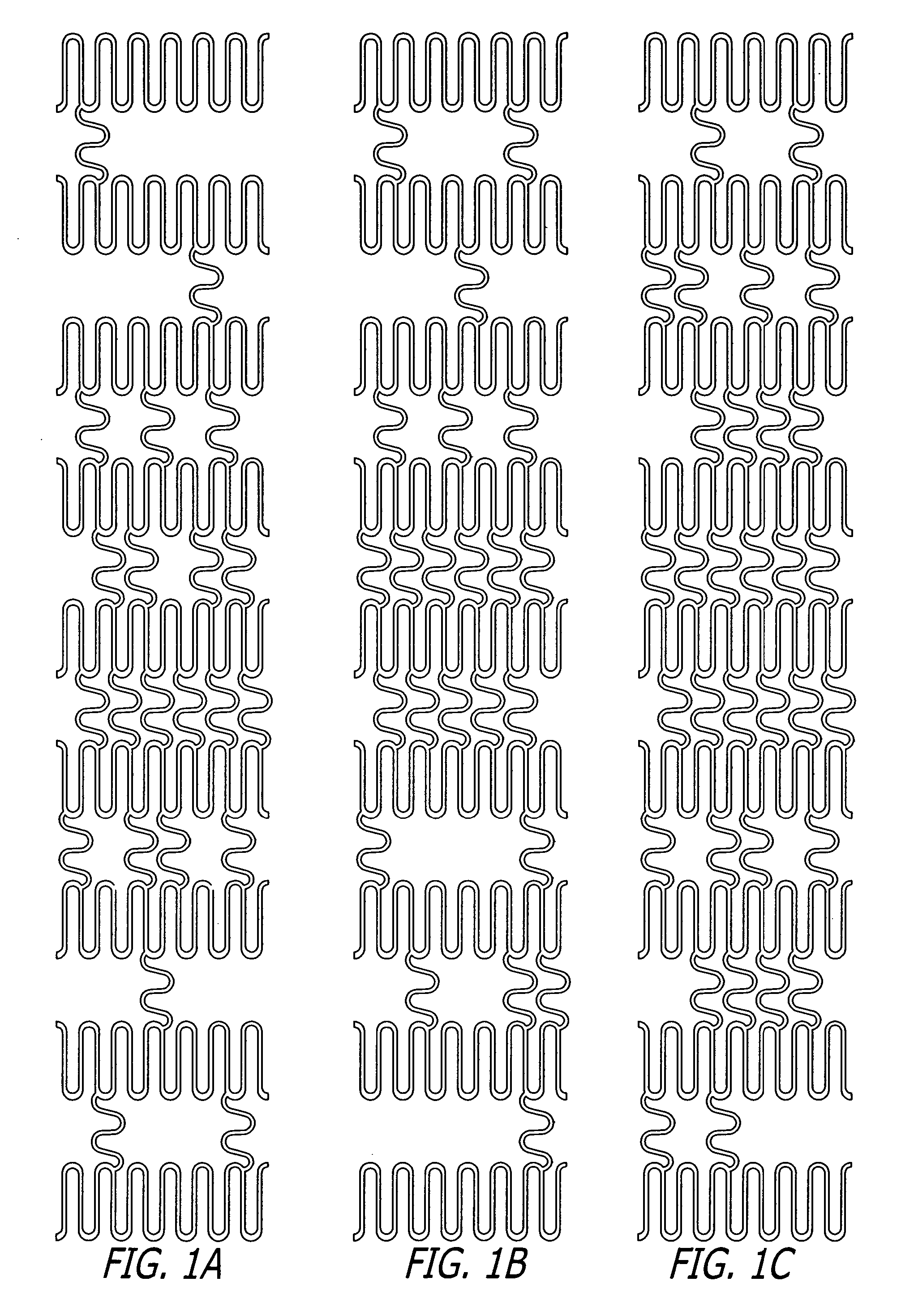
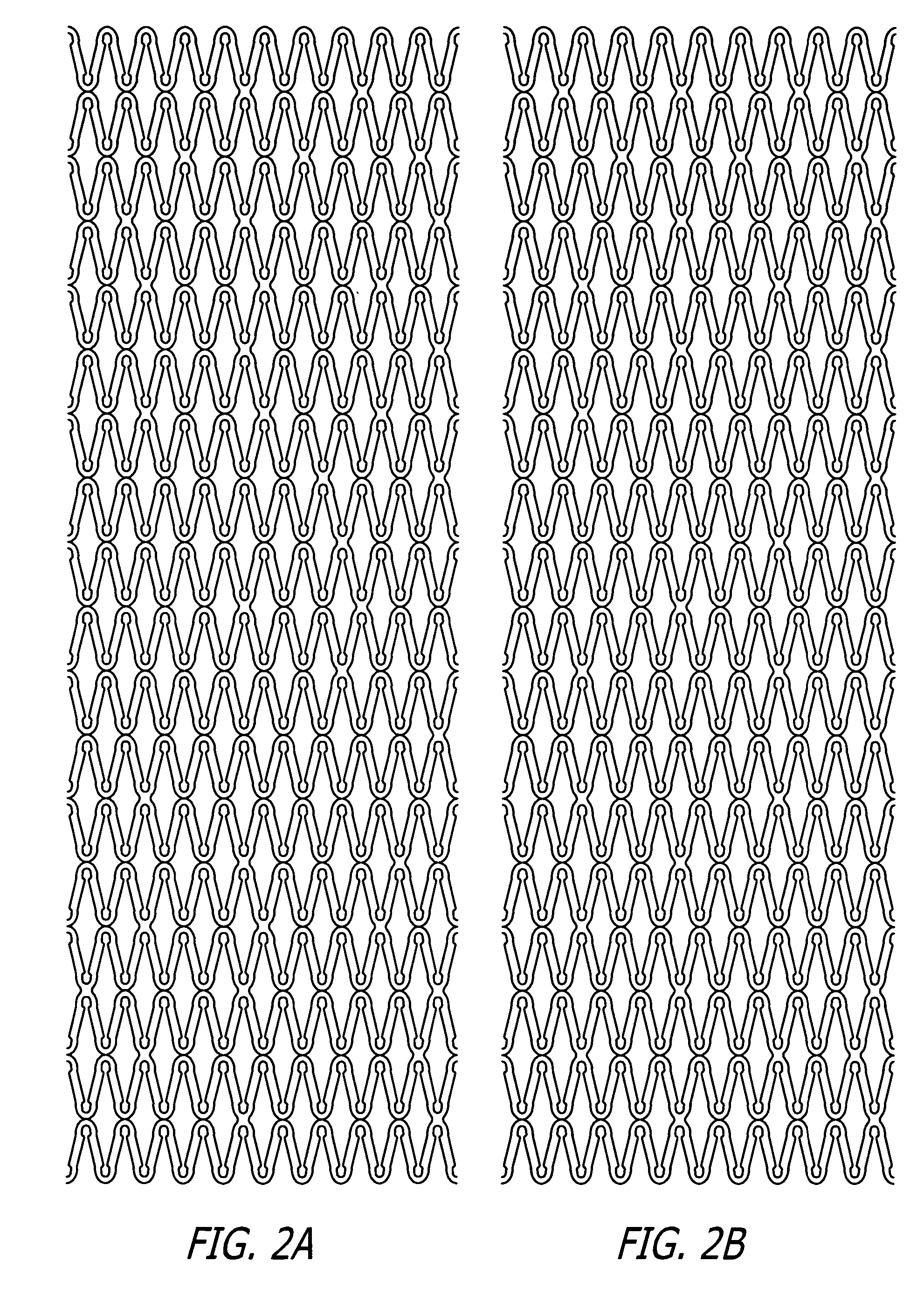
[0036] U.S. Pat. Nos. 5,292,331 and 5,135,536 to Boneau and Hilstead respectively, and the references cited therein, make it clear that stents can be configured and constructed in many different ways. The present invention is applicable to all known stent designs, and it will be readily apparent from the following discussion of several exemplary designs how the invention can be applied to any type of stent construction.

[0037] Illustrative stents of the present invention are included in FIGS. 1-6. The sections of the stents of the present invention can have more or less undulations within a section or more or less sections overall than are shown in the FIGS. 1-6, but the simplified depictions shown herein are sufficient to illustrate the present invention. As stated earlier, the terms “open” and “closed” are to be interpreted as relative to each other within a particular stent. Thus, a portion of a stent that is closed in one stent may be “open” when compared to the closed portion o...


PUM


Abstract

Disclosed herein are various open/closed stent designs and methods for creating the same that can be individually adopted depending on particular treatment objectives. Specifically, the stents of the present invention are manufactured to include different open/closed configurations along their length by varying the number of crossovers, connectors or weld points between sections of the stent. Open portions contain less crossovers, connectors or weld points and are more flexible than closed portions which contain more crossovers, connectors or weld points.

Description

FIELD OF THE INVENTION [0001] This invention relates to implantable medical devices. More specifically, the invention relates to implantable stents for the treatment or inhibition of stenoses in coronary or peripheral vessels in humans. More specifically, the invention relates to various open / closed stent designs and methods for creating the same. BACKGROUND OF THE INVENTION [0002] Cardiovascular disease, including atherosclerosis, is the leading cause of death in the United States. The medical community has developed a number of methods and devices for treating coronary heart disease, some of which are specifically designed to treat the complications resulting from atherosclerosis and other forms of coronary vessel narrowing. [0003] An important development for treating atherosclerosis and other forms of vascular narrowing is percutaneous transluminal angioplasty, hereinafter referred to as “angioplasty.” The objective of angioplasty is to enlarge the lumen of an affected vessel by...

Claims


Application Information

Patent Timeline
IPC IPC(8): A61F2/06A61F2/90
CPCA61F2/90A61F2/91A61F2/915A61F2002/91508A61F2002/91516A61F2002/91533A61F2230/0054A61F2002/91575A61F2002/91583A61F2250/0018A61F2250/0029A61F2230/0013A61F2002/91558
Inventor KLEIN, RICHARD L.PEACOCK, JAMES C. IIILEE, MICHAEL J.
Owner MEDLOGICS DEVICE CORP
Why Eureka
Try Eureka