Storage and retrieval of richly typed hierarchical network models

a hierarchical network model and network model technology, applied in the field of network analysis tools, can solve the problems of incompatibility with new features, large collection of data being required even for relatively small networks, and the inability to store such a network model in relational databases, etc., to achieve efficient search, modification and retrieval of individual nodes, and facilitate search through network hierarchy.

Active Publication Date: 2007-03-01
RIVERBED TECH LLC
View PDF9 Cites 17 Cited by
  • Summary
  • Abstract
  • Description
  • Claims
  • Application Information

AI Technical Summary

Benefits of technology

[0013] It is an objective of this invention to facilitate searches through the network hierarchy that is conventionally masked by the use of a Composite Pattern with BLOB data types. It is a further objective of this invention to allow client applications to modify individual elements within a network model without requiring a deserialization of the entire BLOB hierarchy that is used to store the network model. It is a further objective of this invention to minimize the memory allocation overhead associated with the deserialization of hierarchical BLOBs.
[0014] These objectives, and others, are achieved by providing a Composite Pattern with BLOB data types that includes a path-like construct for locating each component within a network model. Each node in the hierarchy is uniquely identified by a name that is unique within the context of its parent node. The node is also uniquely identified within the entire hierarchy by its “path”, using, for example, a concatenation of the names of the nodes in its ancestry. Database stored procedures are used to efficiently search, modify and retrieve individual nodes from the BLOB using the database server's memory pool so that client applications are not required to retrieve and deserialize the entire Composite-BLOB hierarchy in order to make modifications or search for individual elements, thereby substantially reducing the transfer of data between the application layer and database. To avoid the need for dynamic memory allocation during deserialization, the size of each pre-serialized composite is stored when the composite is serialized, and during deserialization, the size is retrieved and used to obtain sufficient memory for the deserialized composite via a single memory allocation.

Problems solved by technology

To properly emulate the behavior of each device, the configuration parameters, default settings, and so on associated with each device must be captured and included within the models, resulting in a very large collection of data being required even for relatively small networks.
Storing such a network model in a relational database becomes an ongoing challenge in any implementation.
A disadvantage of such an approach, however, becomes apparent when new network routing and switching protocols, configurations, new device types and characteristics are invented and supported by different network equipment manufacturers.
Often, a new capability or characteristic will require a change to the structure of the database schema, and, depending upon the robustness of the original structure, may reveal inherent incompatibilities with the new features and require a substantial restructuring.
A particular disadvantage of this combination of the Composite Pattern and the BLOB data type for storing network models relates to accessing individual elements within the model.
This can prove to be highly CPU and memory inefficient for the large data volumes associated with network models.
In addition to the inherent inefficiency of having to deserialize and serialize the entire network model to access and modify a single network element, the inefficiency of this process is further compounded by the fact that conventional BLOB deserialization processes are generally not well suited to efficiently deserialize ‘unpredictable’ data structures.
As new children are encountered, this block of memory may be insufficiently sized to accommodate the newest child, and an additional block of memory must be allocated.
Additionally, because the block size is generally large, to reduce the required number of reallocations, substantial memory space can be wasted at each composite structure, when a new block is allocated but not filled by the remaining data.

Method used


Image

  • Storage and retrieval of richly typed hierarchical network models
  • Storage and retrieval of richly typed hierarchical network models
  • Storage and retrieval of richly typed hierarchical network models

Examples


Embodiment Construction

[0021] In the following description, for purposes of explanation rather than limitation, specific details are set forth such as the particular architecture, interfaces, techniques, etc., in order to provide a thorough understanding of the concepts of the invention. However, it will be apparent to those skilled in the art that the present invention may be practiced in other embodiments, which depart from these specific details. In like manner, the text of this description is directed to the example embodiments as illustrated in the Figures, and is not intended to limit the claimed invention beyond the limits expressly included in the claims. For purposes of simplicity and clarity, detailed descriptions of well-known devices, circuits, and methods are omitted so as not to obscure the description of the present invention with unnecessary detail.

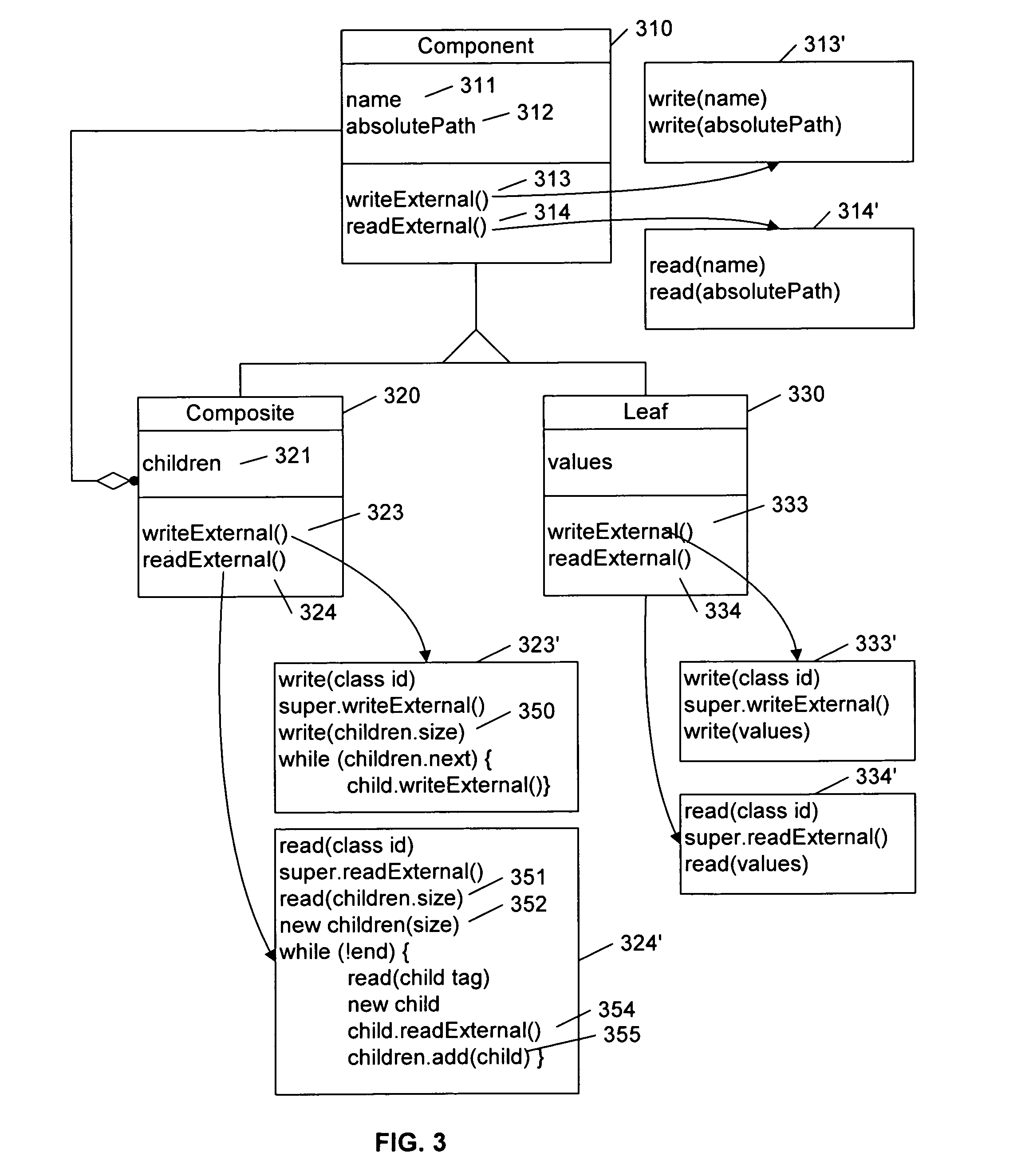
[0022] In this disclosure, the examples are presented using classes, methods, and structures common to the Java Programming Language. However,...


PUM


Abstract

A Composite Pattern with BLOB data types is used to model a hierarchical network, and includes a path-like construct for locating each component within the network model. Database procedures are used to efficiently search, modify and retrieve individual nodes from the network model using the database server's memory pool so that client applications are not required to retrieve and deserialize the entire Composite-BLOB hierarchy in order to make modifications or search for individual elements, thereby substantially reducing the transfer of data between the application layer and database. To avoid the need for dynamic memory restructuring during deserialization, the size required to store component data at each composite is stored when the composite is serialized, and during deserialization, the size is retrieved and used to obtain sufficient memory for the deserialized composite.

Description

[0001] This application claims the benefit of U.S. Provisional Patent Application 60 / 709,768, filed 19 Aug. 2006.BACKGROUND AND SUMMARY OF THE INVENTION [0002] This invention relates to the field of network analysis tools and other tools that use a relational database to store and retrieve hierarchical data in a generic and schema agnostic fashion. [0003] The effective management of large networks requires the use of tools that use one or more models of the network and each component within the network. To model the performance of a network, simulators and other tools effectively emulate the behavior of each of the devices in the network to determine how the system will perform as message traffic is propagated across the network, or to facilitate the diagnosis of the network as problems are reported. To properly emulate the behavior of each device, the configuration parameters, default settings, and so on associated with each device must be captured and included within the models, r...

Claims


Application Information

Patent Timeline
Patent Type & Authority Applications(United States)
IPC IPC(8): G06F7/00
CPCG06F17/30607G06F16/289
Inventor GEORGE, ZACHARIAHANSEN, TODD WILLIAMSHAH, AMISH
Owner RIVERBED TECH LLC
Why Eureka
Try Eureka