
Operating device, position-switching device, and magneto-optical recording/reproducing device

a technology of positioning switch and operating device, which is applied in the direction of light beam reproducing, machines/engines, instruments, etc., can solve the problems of large thickness of portable md recorders, high motor cost, and reduce the height of operating devices, so as to increase the swinging angle of the drive lever, reduce the thickness of the operating device, and reduce the manufacturing cost

Inactive Publication Date: 2007-03-01
PANASONIC CORP
View PDF25 Cites 3 Cited by
  • Summary
  • Abstract
  • Description
  • Claims
  • Application Information

AI Technical Summary

Benefits of technology

"The present invention provides an operating device that can repeatedly rotate a lifter without the need for a motor or other power source. The device includes a pair of linear members made of shape memory alloy that contract and extend due to heat generated by electrification. The movable member of the device is a drive lever that is connected to the linear members and can be rotated to cause the lifter to move between an active position and an inactive position. The invention also includes a locking unit for locking the drive lever in position. The linear members act as a driving force source, and the tension generated by the shrinkage of the linear members causes the movable member to rotate. The invention reduces the thickness of the operating device and lowers manufacturing costs."

Problems solved by technology

Since it is difficult to reduce this height, a portable MD recorder has a large thickness.
Moreover, the motor is expensive.
For this reason, the number of components increases and the manufacturing cost rises.
The control of an electric signal also tends to become complicated in order to improve trackability for the electric signal.
Similar problems rise even if a plunger is used instead of the motor 117.
The size of the mechanism is determined by the size of the plunger and the plunger causes high cost.

Method used


Image

  • Operating device, position-switching device, and magneto-optical recording/reproducing device
  • Operating device, position-switching device, and magneto-optical recording/reproducing device
  • Operating device, position-switching device, and magneto-optical recording/reproducing device

Examples


Embodiment Construction

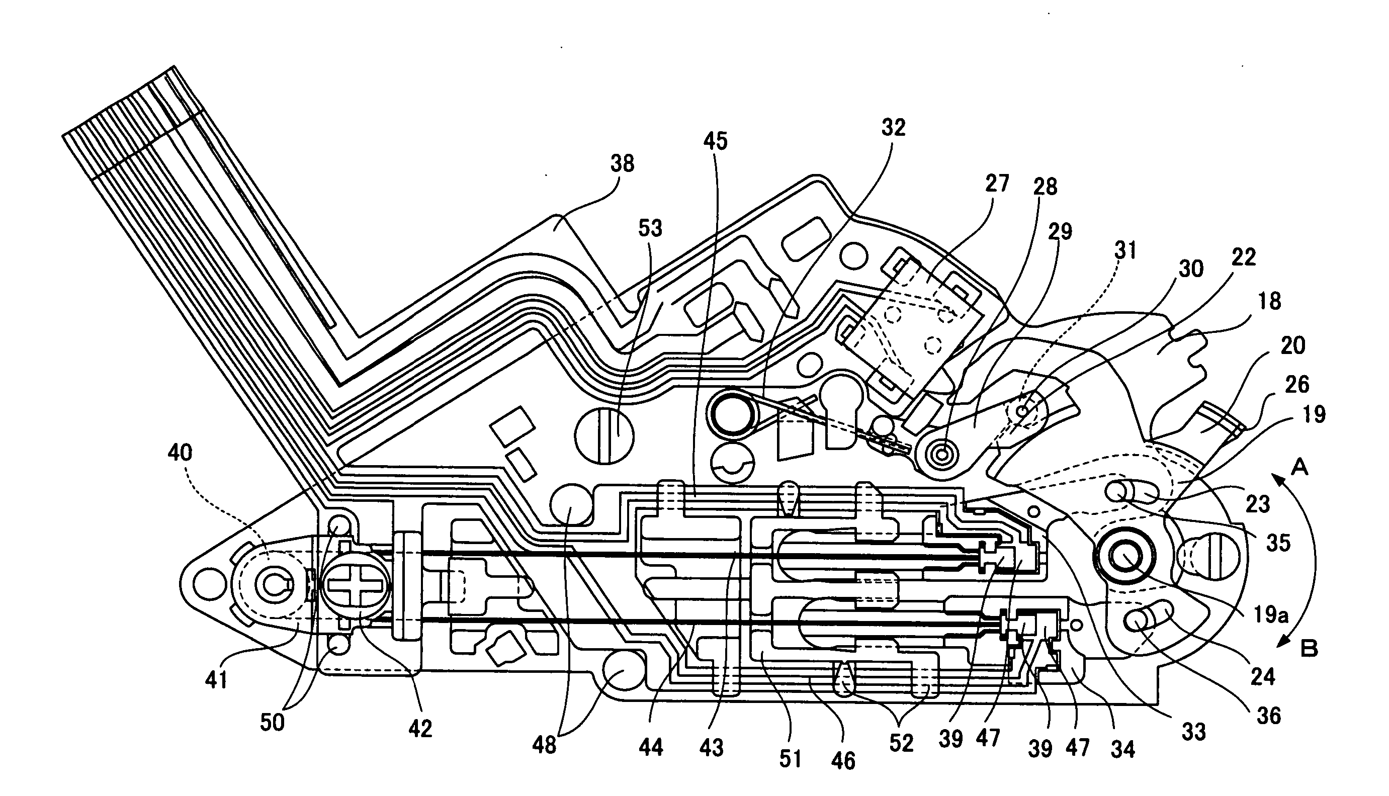
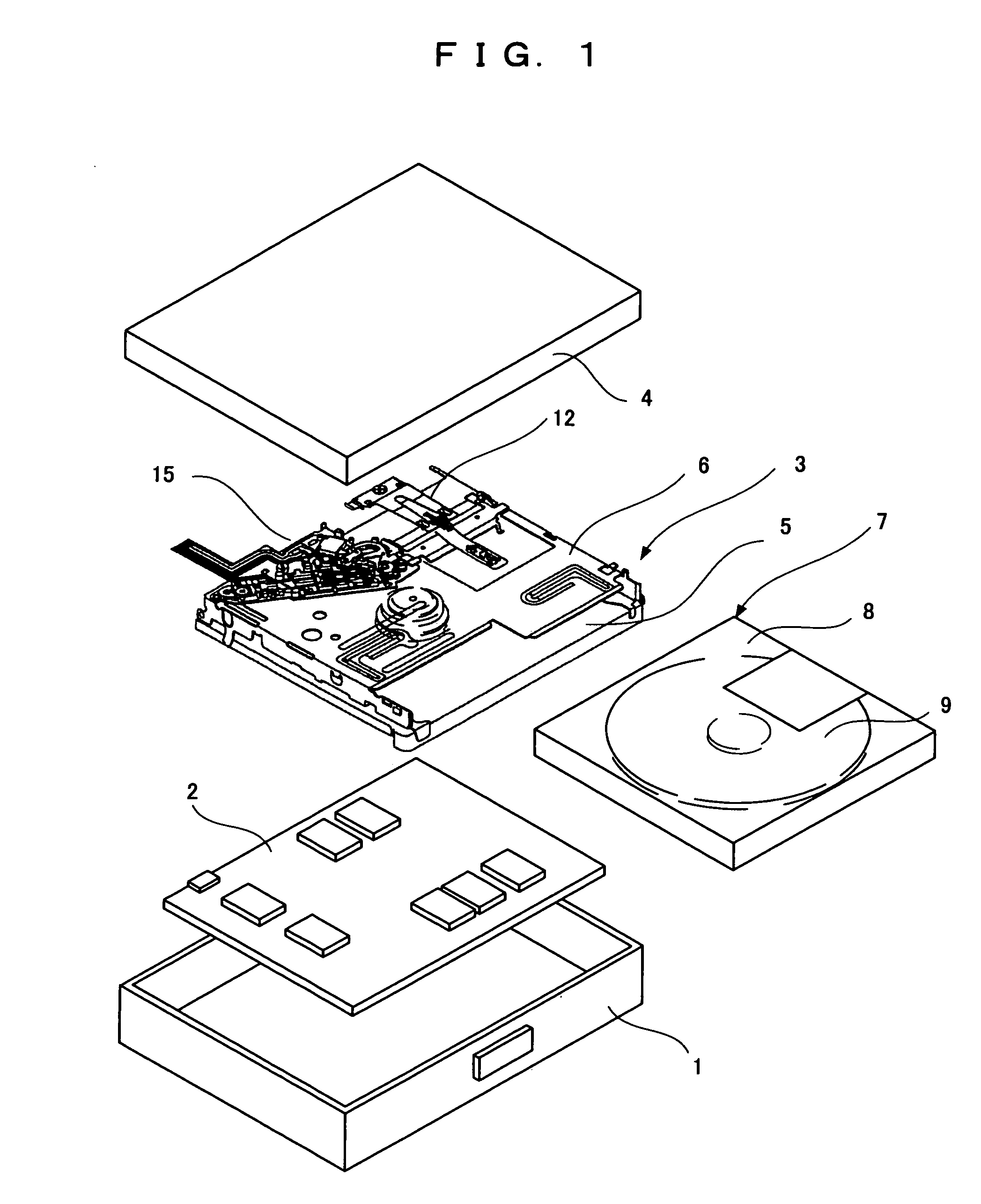
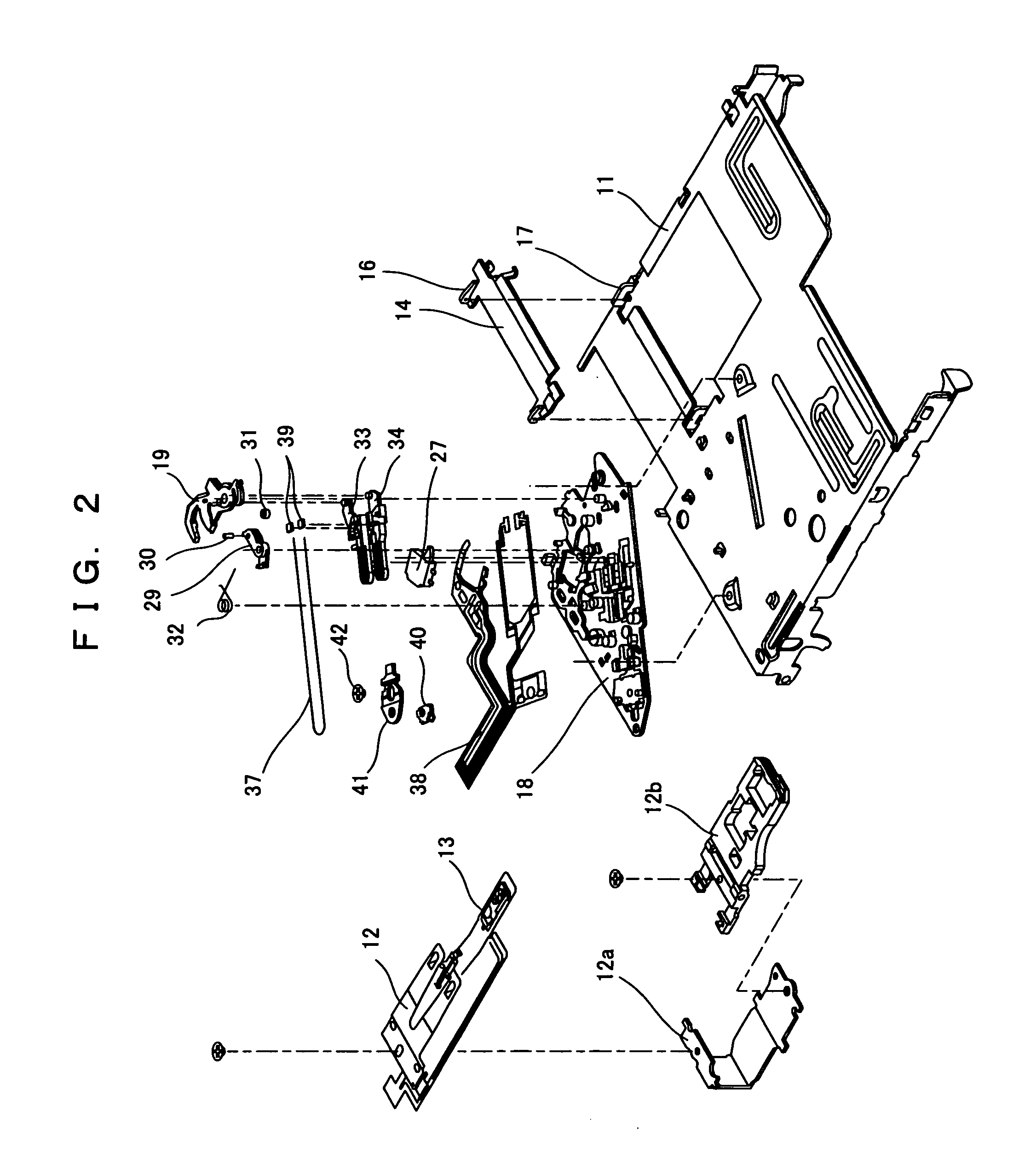
[0076] Embodiments of the present invention will be discussed below in accordance with the accompanying drawings. FIG. 1 is an exploded perspective view schematically showing a magneto-optical recording / reproducing apparatus of the present embodiment. FIG. 2 is an exploded perspective view showing the magneto-optical recording / reproducing apparatus. FIG. 3 is an exploded perspective view showing the principle part of the magneto-optical recording / reproducing apparatus.

[0077] As shown in FIGS. 1 to 3, in the magneto-optical recording / reproducing apparatus, an electric circuit 2 and a mechanical mechanism 3 are stored in a body cabinet 1 and a lid 4 covers the opening of the body cabinet 1.

[0078] The mechanical mechanism 3 comprises a mechanical base 5 and a mechanical part 6 placed on the mechanical base 5. A mini disc 7 loaded in a storage space between the mechanical base 5 and the mechanical part 6 has an optical disc 9, on which signals such as a music signal can be recorded an...


PUM

PropertyMeasurementUnit
diameteraaaaaaaaaa
tensionaaaaaaaaaa
forceaaaaaaaaaa

Abstract

An operating device has a pair of linear members (43, 44) made of a shape memory alloy and contracting axially due to heat generated by electrification and generating tension in the contracting direction, a drive lever (19) supported to pivot about a pivot shaft (19a), a pair of drive rods (33, 34) respectively connected to both sides of the drive lever (19) with the pivot shaft (19a) being disposed between the sides of the drive lever (19), and a power supply circuit for selectively electrifying the linear members (43, 44). One end of each of the linear members (43, 44) is fixed to a stationary member, and the other end is connected to each of the drive rods (33, 34).

Description

TECHNICAL FIELD [0001] The present invention relates to a magneto-optical recording / reproducing apparatus capable of recording and reproducing information on a disc and a position switching device preferably used for the magneto-optical recording / reproducing apparatus, and specifically relates to an operating device and a position switching device for switching the position of a magnetic head unit in response to the driving of the operating device. BACKGROUND ART [0002] In recent years, magneto-optical recording / reproducing apparatuses have become compact with higher performance, in which reading and reproducing are performed by optical pickups on optical discs acting as recording mediums. Portable MD recorders using MiniDisc (MD) have become generally available as such portable magneto-optical recording / reproducing apparatuses with smaller size and higher performance. [0003] A conventional magneto-optical recording / reproducing apparatus is disclosed in, for example, Japanese Patent...

Claims


Application Information

Patent Timeline
Patent Type & Authority Applications(United States)
IPC IPC(8): G11B7/00G11B11/105F03G7/06G11B21/08G11B21/12
CPCF03G7/065G11B11/10558G11B21/083G11B21/12
Inventor KUBO, KENJISHINOHARA, ISAO
Owner PANASONIC CORP
Learn More