Modular housing system and method of manufacture

Inactive Publication Date: 2007-03-08
WALL HARLIN
View PDF6 Cites 12 Cited by
  • Summary
  • Abstract
  • Description
  • Claims
  • Application Information

AI Technical Summary

Benefits of technology

[0013] Perforated rolled shapes used in both the transverse and longitudinal direction of the floor, ceiling, and roof panels, and the vertical exterior and marriage walls of the modules perform the multi-function of energy conservation and distribution of mechanical, plumbing, and electrical access to transfer services within and between the modules composing the stru

Problems solved by technology

However, the current modular industry has not yet achieved full integration of mechanical and utility services as part of an automated production system and is still reliant upon labor intensive technology, historic materials and outdated modes of structural framing.
In addition to requiring weeks to finish a typical 2,000 ft2 house, the industry wastes time and money with outmoded transport methods.
The second method requires expensive, heavy steel framed multi-axle transport trailers to limit damage to gypsum and other relatively soft interior finishes due to module flexion during transport.
Currently the industry standard is far from the ideal product of a complete module including integrated mechanical and utility services, full insulation and efficient use of materials.
Although certain modular industry products approximate the ideal, the mainstream modular industry has developed without the structural, cost and aesthetic advantage of galvanized light gage steel rolled shapes and automated production technologies.
Despite the potential, light gauge steel has not historically been economical primarily due to difficult connection problems.
The attachment of light gauge steel shapes to construct panels for modular structures, limited by national codes and conventions

Method used


Image

  • Modular housing system and method of manufacture
  • Modular housing system and method of manufacture
  • Modular housing system and method of manufacture

Examples


Embodiment Construction

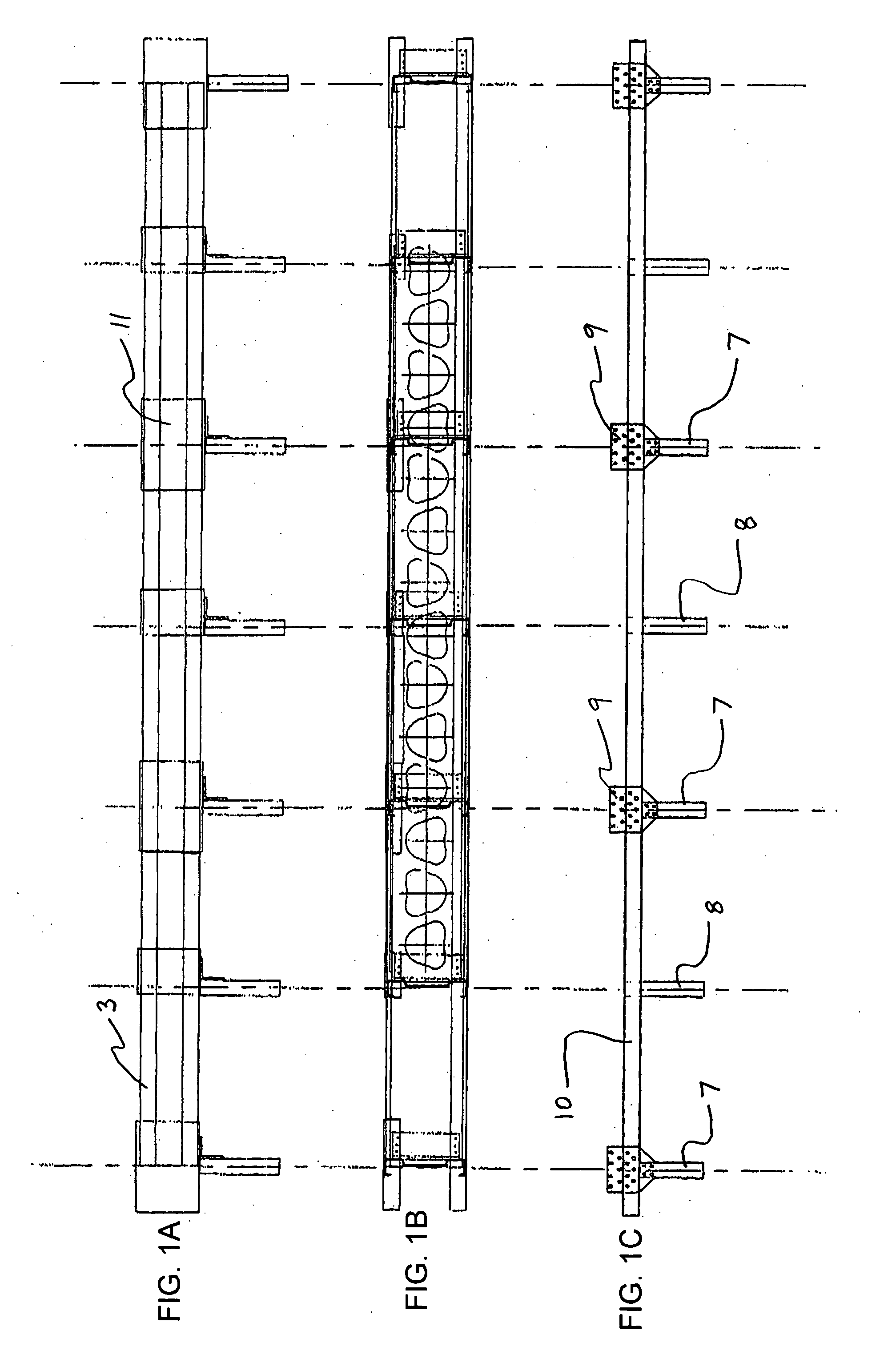
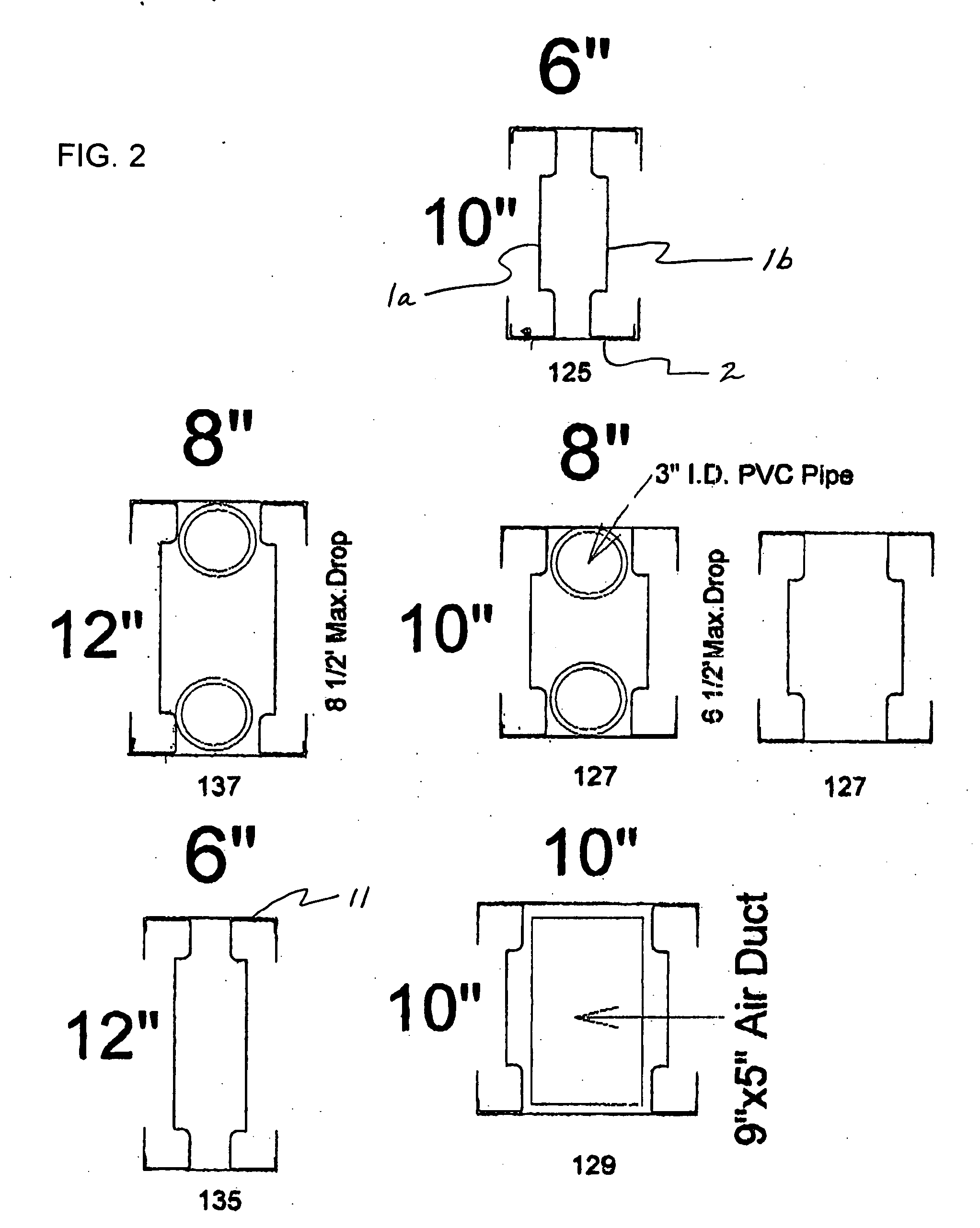
[0029] As shown in FIGS. 1A to 1C, an edge beam (EB) (3) is constructed of two vertical perforated rolled shapes (1a, 1b) having webs that are inverted toward the center of the beam and one bottom track (2) with the flanges in a vertical position against the bottom lips of the vertical rolled shapes. The two vertical members and the bottom track compose a U-shaped edge beam (3) having an open top to permit the insertion of mechanical and utility distribution in the longitudinal and transverse edge beams of the modules. The two vertical perforated rolled shapes (1a, 1b) function as compression members of the edge beam.

[0030] The three basic components of the edge beam are positioned so as to provide access for the press joining tools. In particular, the construction of the edge beams permits automatic insertion of the tool head so that the bottom flanges of the compression members can be press joined directly to the web of the bottom track (2) along the full length of the edge beam ...


PUM

PropertyMeasurementUnit
Fractionaaaaaaaaaa
Fractionaaaaaaaaaa
Mechanical propertiesaaaaaaaaaa

Abstract

An edge beam construction including two vertical perforated rolled shapes with webs inverted toward the center of the beam, and a bottom track having a flange disposed in a vertical position against bottom lips of the vertical rolled shapes. The three basic components of the edge beam are positioned so as to provide access for press joining tools. A building module manufacturing method utilizes the light gauge steel rolled shapes that permit industrialized, automated manufacture of floor, roof and wall panels for modular housing and commercial structures with integrated mechanical and electrical systems and rigid framing for road transport without trailers. The module manufacturing method includes a novel method of constructing and positioning a gable.

Description

[0001] This application claims the benefit of U.S. Provisional Application No. 60 / 714371, filed Sep. 7, 2005, the entire contents of which are incorporated herein by reference.BACKGROUND OF THE INVENTION [0002] 1. Field of the Invention [0003] The present invention relates to a novel method of industrial, automated manufacture of light gage steel floor, roof and wall panels, with exceptional energy properties, to form stronger building modules of varying width, height and length. The invention provides structures of one to four stories for homes, offices, motels, hotels and other cellular structures. The method also allows aesthetic flexibility for a wide range of products, from traditional family home designs to contemporary structures including large glass surfaced areas and spatial elements. The invention uses lighter weight materials; thereby reducing module weight by approximately 40% of modules produced by the current wood modular industry and significantly reduces shipping co...

Claims


Application Information

Patent Timeline
IPC IPC(8): E04C3/30
CPCE04B1/34336Y10T29/49627E04B7/20E04C2/384E04C3/083E04C2003/0439E04C2003/0452E04C2003/0491Y10T29/49623Y10T29/53365Y10T29/53374Y10T29/49622Y10T29/49634Y10T29/49616E04B5/02
Inventor WALL, HARLIN
Owner WALL HARLIN
Why Eureka
Try Eureka