
Barless closed loop color control

a closed loop, color control technology, applied in the direction of digitally marking record carriers, instruments, printing press parts, etc., can solve the problems of labor intensive, slow manual control methods, and inferior color quality of multi-colored images,

Inactive Publication Date: 2007-03-08
INNOLUTIONS
View PDF17 Cites 25 Cited by
  • Summary
  • Abstract
  • Description
  • Claims
  • Application Information

AI Technical Summary

Benefits of technology

[0027] The invention provides a process for measuring and controlling the color value of one or more colored image portions which are printed on a planar substrate in a plurality o

Problems solved by technology

An inaccurate ink density setting for any of the colors may result in a multi-colored image of inferior color quality.
However, this assumption is not always correct.
However, such manual control methods tended to be slow, relatively inaccurate, and labor intensive.
The visual inspection techniques used in connection with ink key presetting and color control are inaccurate, expensive, and time-consuming.
Further, since the required image colors are often halftones of ink combined with other ink colors, such techniques also require a high level of operator expertise.
Ink key opening presets are just an approximation and may not be a perfect setting.
It is well known that the light intensity from flash to flash with such a device is not consistent.
This becomes a problem in color measurement since variation in flash intensity provides false readings.
Another problem with xenon strobes is that they work with higher voltage and drive electronics generate electrical noise and heat.
These features make it more difficult to package a camera and xenon strobe in a single sealed imaging assembly.
Unfortunately, measuring the color of a printed substrate using a color bar has several disadvantages.
However, this assumption is not always correct.
Second, the color bar requires additional space on the substrate.
Depending on job configuration, this space may not be available.
Further, this additional substrate space is not part of the finished product, so it increases the cost of production.
In addition, there are associated trimming costs for printed products for which a color bar is objectionable, thereby increasing the cost of the operation, as well as the costs associated with removing and disposing of trimmed color bar waste.
For different press configurations and job requirements, it may or may not be possible to have color bars.
While a color bar may have some advantages, the job and press configuration may not allow having a color bar.
In such a case, the operator has to adjust the press by visually inspecting the image or by measuring the color value within the print using a hand held densitometer, and the operator has to choose the places where he would like to measure the color value, and the densitometer readings may not be correct if colors are mixed in the area being inspected.
The operation requires a lot of computation power making it very expensive and slow.
These requirements make it practically impossible to implement Closed Loop Color Control without a color bar.
This would also require a lot of computation power since images in the same ink zone have to be captured, aligned to the pre-press image, processed and analyzed.
Since color values read from the camera are dependent on the amount of light received by the sensor in a specific time, this method becomes speed sensitive.
Both solutions suffer from inherent inaccuracies and errors making it practically very difficult to implement this solution.
This system is further disadvantageous because the light reflected from non-printed areas also gets integrated into the frame.
If there is a very small area being printed on the key zone, the image of printed area gets diluted by the image of the non-printed area of the substrate to a point where the final frame may not be able to provide enough resolution information about the printed color.
The disadvantage of this system is that the light reflected from non-printed areas also gets integrated in the frame.
If there is a very small area being printed on the key zone, the image of printed area gets diluted by the image of the non-printed area of the substrate to a point where the integrated frame may not be able to provide enough resolution information about the printed color.

Method used


Image

  • Barless closed loop color control
  • Barless closed loop color control
  • Barless closed loop color control

Examples


Embodiment Construction

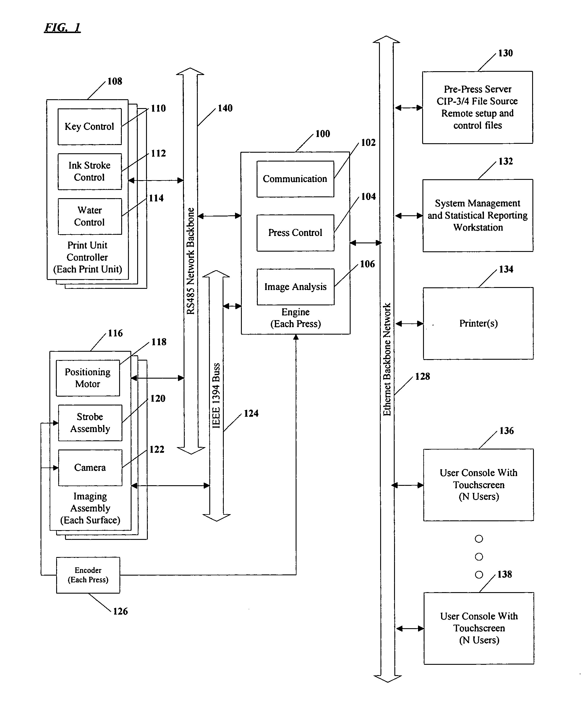
[0099] The invention provides a system and processes for measuring and controlling the color values of one or more colored images or colored image portions during operation of a printing press, such as sheet fed and web presses, and offset and other printing processes. The images comprise one or more colors and are printed on a moving, planar substrate in a plurality of ink zones that extend across a width of the substrate. An imaging assembly selects and acquires images of a moving substrate, determines a relationship between actual and target color values, and automatically makes any necessary ink quantity adjustments.

[0100] A typical rotary printing process utilizes printing cylinders having printing plates attached thereto. Conventionally, a positive or negative image is put onto a printing plate using standard photomechanical, photochemical or laser engraving processes. Ink is then applied to the plate's image area and transferred to the substrate. A single printing plate is g...


PUM


Abstract

A system and processes for the accurate measurement and control of image color values on a printing press with or without the presence of a color bar. More particularly, a barless color control system and processes for controlling the color quality of color images printed on a substrate online or offline, with or without a color bar printed on the substrate. The system provides an efficient and inexpensive method for barless closed loop color control and the processes are conducted without pixel-by-pixel comparisons.

Description

BACKGROUND OF THE INVENTION [0001] 1. CD-ROM Appendix [0002] The computer program listing appendix referenced, included and incorporated in the present application is included in a single CD-ROM appendix labeled “BARLESS CLOSED LOOP COLOR CONTROL” which is submitted in duplicate. The CD-ROM appendix includes 82 files. The computer program is incorporated herein by reference. [0003] 2. Field of the Invention [0004] The present invention relates to a system for the accurate measurement and control of image color values on a printing press with or without the presence of a color bar. More particularly, the invention provides a barless color control system and processes for controlling the color quality of color images printed on a substrate online or offline, with or without a color bar printed on the substrate. [0005] 3. Description of the Related Art [0006] Color perception of a printed image by the human eye is determined by the light reflected from an object, such as a printed subs...

Claims


Application Information

Patent Timeline
IPC IPC(8): G01N19/02
CPCB41F33/0036B41P2233/51B41F33/0081B41F33/0045
Inventor FRIEDMAN, MICHAELPATEL, MANOJKUMARWESTBERG, BRUCEPATEL, PIYUSHKUMAR
Owner INNOLUTIONS
Learn More