Reader/writer and mobile communication apparatus

a mobile communication and writing technology, applied in the direction of near-field systems using receivers, instruments, sensing by electromagnetic radiation, etc., can solve the problem of difficult to incorporate control substrates and antenna substrates into mobile communication apparatuses

Active Publication Date: 2007-03-08
MURATA MFG CO LTD
View PDF16 Cites 51 Cited by
  • Summary
  • Abstract
  • Description
  • Claims
  • Application Information

AI Technical Summary

Benefits of technology

[0009] In order to overcome the problems described above, preferred embodiments of the present invention provide a reader/writer that can be co

Problems solved by technology

However, it is very difficult to incorporate a control substrate and an antenna s

Method used


Image

  • Reader/writer and mobile communication apparatus
  • Reader/writer and mobile communication apparatus
  • Reader/writer and mobile communication apparatus

Examples


first preferred embodiment

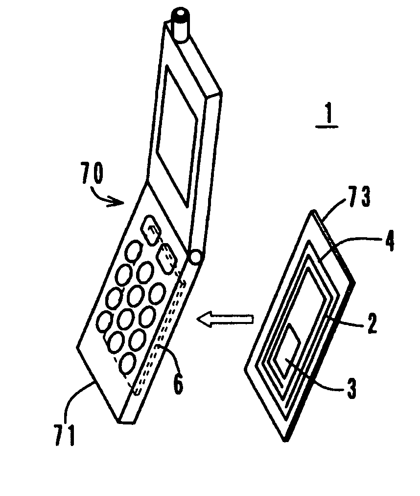
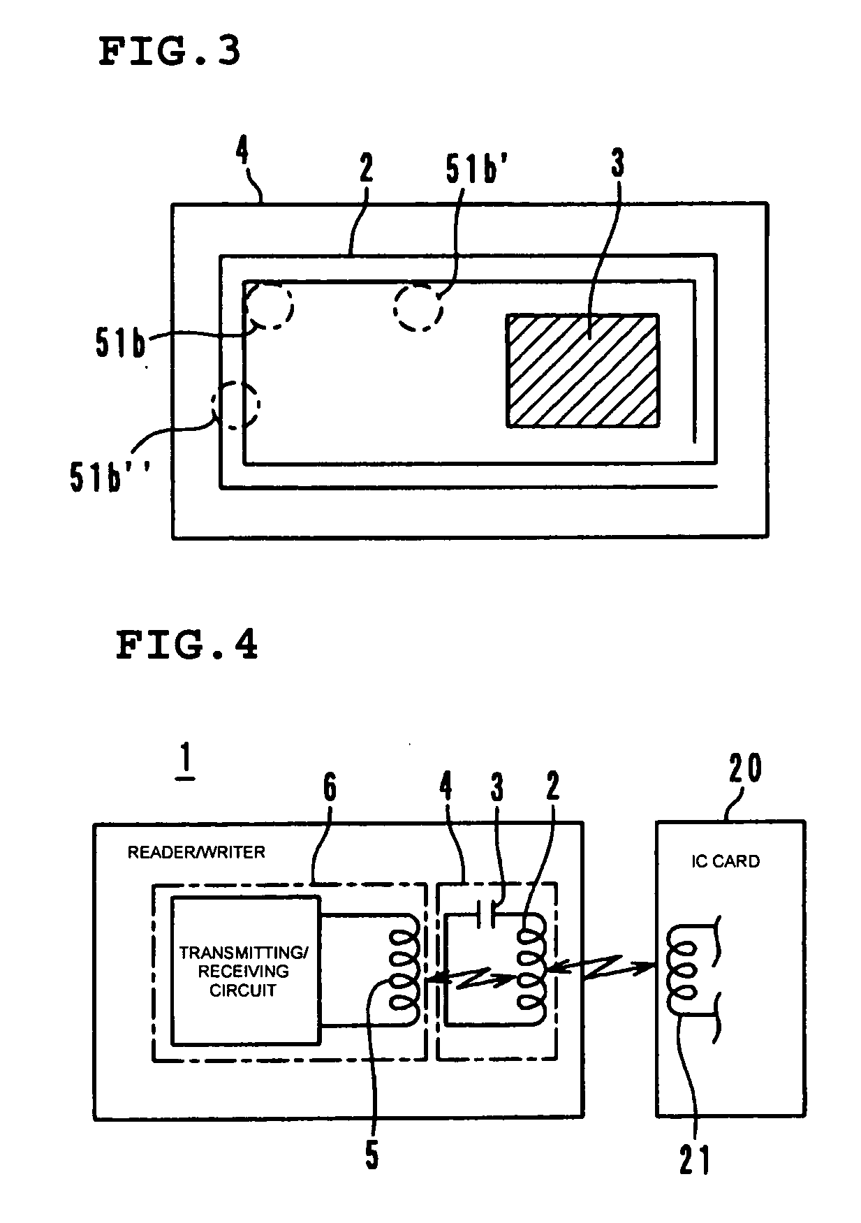
[0034]FIG. 1 is an exploded perspective view of a non-contact reader / writer 1 for an IC card, and FIG. 2 is a vertical cross-sectional view thereof. The non-contact reader / writer 1 for an IC card includes an antenna substrate 4 provided with a loop antenna 2 and a capacitor 3 on its upper surface, a control substrate 6 provided with a transmitting / receiving circuit (not shown) and a chip coil 5 on its upper surface, a magnetic sheet 10 placed between the antenna substrate 4 and the control substrate 6, and an insulating case 15.

[0035] The chip coil 5 on the control substrate 6 is longitudinally wound and includes a magnetic core 51 having a lower flange portion 51a, a body portion 51b, and a winding 52 wound on the body portion 51b. The chip coil 5 is arranged such that the coil axis thereof is vertical to the control substrate 6 and such that the open end surface of the body portion 51b is directed above. The chip coil 5 is a coil of an open magnetic circuit type to emit a magneti...

second preferred embodiment

[0046] A non-contact reader / writer 1A for an IC card according to a second preferred embodiment is thinner than the reader / writer 1 for an IC card according to the first preferred embodiment. As shown in FIGS. 5 and 6, the antenna substrate 4 is provided with an opening 4a inside the loop antenna 2. The upper portion of the chip coil 5 is placed through the opening 4a.

[0047] In the reader / writer 1A for an IC card having the above-described configuration, the upper portion of the chip coil 5 is accommodated in the opening 4a of the antenna substrate 4, and thus the height thereof can be reduced accordingly. Furthermore, the magnetic coupling between the chip coil 5 and the loop antenna 2 can be further strengthened.

third preferred embodiment

[0048] As shown in FIGS. 7 and 8, in a non-contact reader / writer 30 for an IC card according to a third preferred embodiment, a plurality of (four) chip coils 5 are provided on the control substrate 6 in a rotationally symmetrical pattern. The respective chip coils 5 may be electrically connected either in series or in parallel, but should be connected so that the magnetic fluxes generated by the chip coils 5 have the same polarity.

[0049] With this configuration, magnetic fluxes generated by current flowing through the respective chip coils 5 are cancelled to some extent between adjacent chip coils 5, and thus a magnetic flux distribution equivalent to that of a large coil can be obtained. Therefore, sufficient magnetic coupling with the loop antenna 2 can be ensured even if each of the chip coils 5 is small. Further, by using the plurality of chip coils 5, the magnetic coupling does not degrade even if the chip coils 5 are slightly misaligned with the loop antenna 2, and thus the ...


PUM


Abstract

A non-contact reader/writer for an IC card includes an antenna substrate provided with a loop antenna and a capacitor on its upper surface, a control substrate provided with a transmitting/receiving circuit and a chip coil on its upper surface, and a magnetic sheet disposed between the antenna substrate and the control substrate. A magnetic flux generated by the chip coil on the control substrate passes through the loop antenna to cause magnetic coupling, so that the loop antenna and the transmitting/receiving circuit need not be connected to each other through a communication cable.

Description

BACKGROUND OF THE INVENTION [0001] 1. Field of the Invention [0002] The present invention relates to a reader / writer and a mobile communication apparatus, and more particularly to a reader / writer communicating with an IC card or the like in a non-contact manner and a mobile communication apparatus such as a mobile phone. [0003] 2. Description of the Related Art [0004] Readers / writers for an IC card, performing communication in a non-contact manner by using magnetic coupling, have been known (e.g., see Japanese Unexamined Utility Model Registration Application Publication No. 6-13214 and Japanese Unexamined Patent Application Publication No. 11-288447). These known readers / writers 100 for an IC card include an antenna substrate 101 provided with a loop antenna 102 on its upper surface and a control substrate 103 provided with a transmitting / receiving circuit (not shown) on its upper surface, as shown in FIG. 13. [0005] The loop antenna 102 is a printed coil provided on the upper surf...

Claims


Application Information

Patent Timeline
IPC IPC(8): G06K7/08G06K7/00G06K7/10G06K17/00G06K19/077H01Q7/00H04B1/59H04B5/02
CPCG06K7/0008G06K7/10336H04B5/02H04B5/0056G06K19/07749
Inventor YAMAGUCHI, KOICHI
Owner MURATA MFG CO LTD
Why Eureka
Try Eureka