
Field emitting light source and method for making the same

a field-emitting light source and carbon nanotube technology, applied in the manufacture of electrode systems, electric discharge tubes/lamps, discharge tubes luminescnet screens, etc., can solve the problems of high cost and limited application of small-sized light sources, and achieve the effect of long operation life and suitability for mass production

Active Publication Date: 2007-03-08
TSINGHUA UNIV +1
View PDF6 Cites 21 Cited by
  • Summary
  • Abstract
  • Description
  • Claims
  • Application Information

AI Technical Summary

Benefits of technology

[0010] Another advantage of the present light source is it is cheaper and suitable for mass production.
[0011] A further advantage of the present light source is that the CNTs are firmly fixed on the cathode and not likely to break off, thus the light source has a longer operation lifetime.

Problems solved by technology

However, both of the foregoing methods are expensive and limited for small size light sources.

Method used


Image

  • Field emitting light source and method for making the same
  • Field emitting light source and method for making the same
  • Field emitting light source and method for making the same

Examples


Embodiment Construction

[0017] Reference will now be made to the drawings to describe the preferred embodiments of the present light source, in detail.

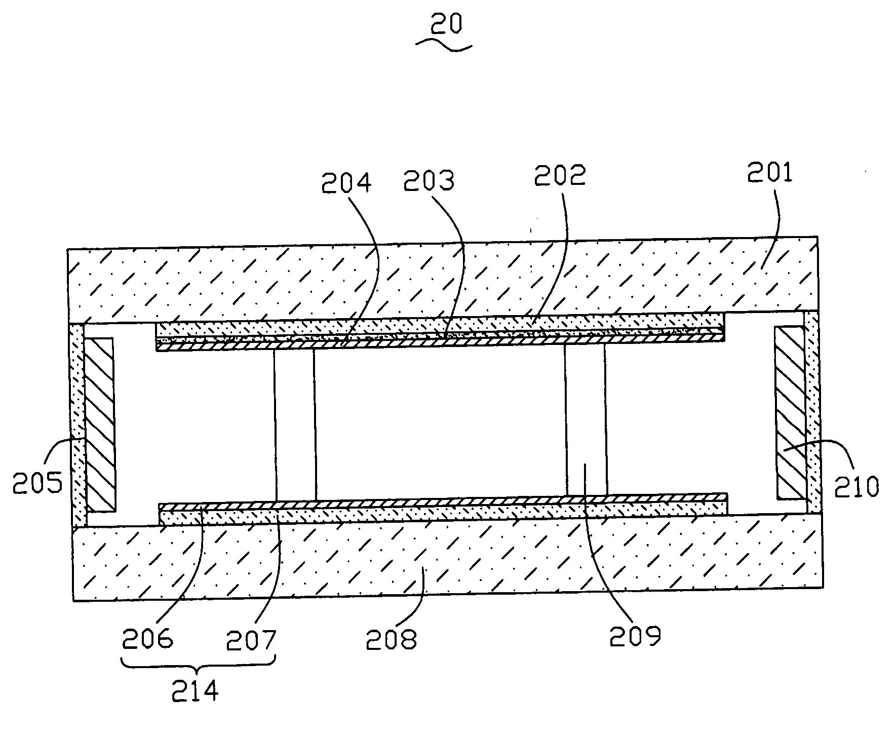
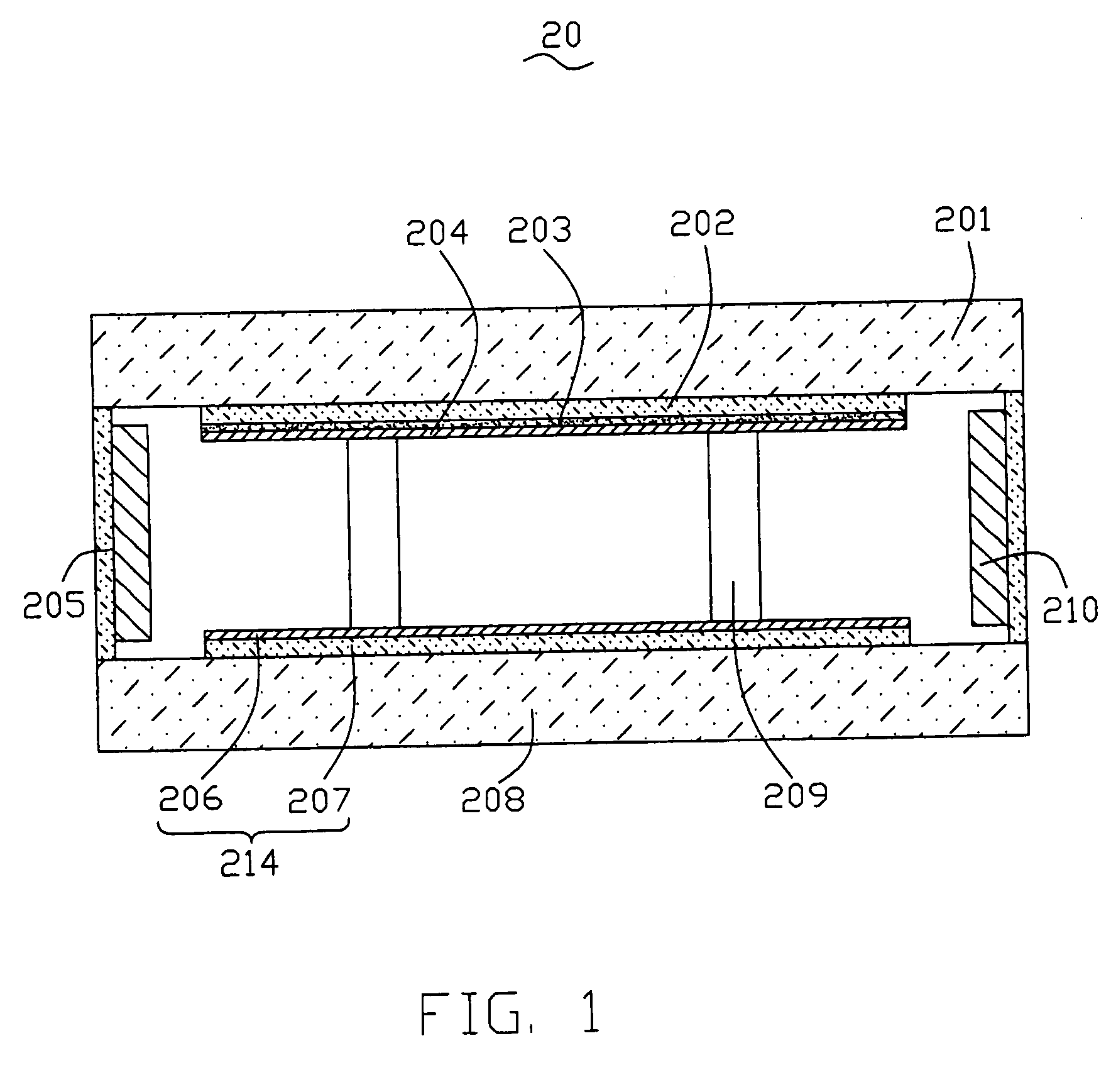
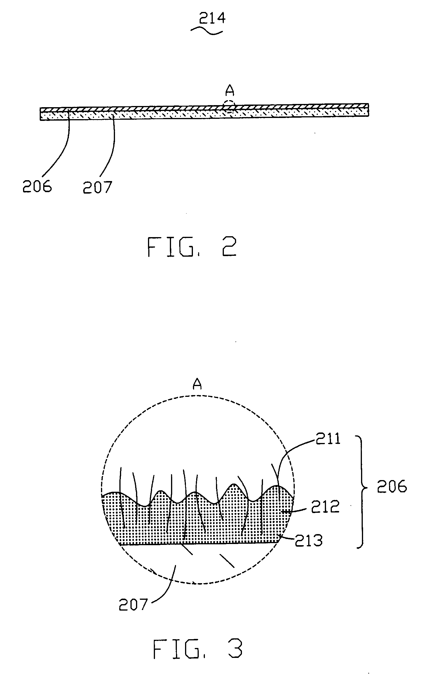
[0018] Referring now to the drawings, and more particularly to FIG. 1, there is shown a light source 20. The light source 20 mainly includes an anode 202, an anode substrate 201, a cathode 214, a cathode substrate 208, a fluorescent layer 203, and a sealing means 205. The cathode 214 includes an emitter layer 206, and a conductive layer 207. The conductive layer 207 is sandwiched between the cathode substrate 208 and the emitter layer 206 for providing an electrical connection therebetween. The anode 202 is configured on the anode substrate 201, and the cathode 214 is configured on the cathode substrate 208. The anode 202 and the cathode 214 are oppositely configured to produce a spatial electrical field when a voltage is applied therebetween, such a spatial electrical field being capable of enabling emitters (not shown in FIG. 1) of the emitter layer 206 t...


PUM


Abstract

A CNT field emitting light source (20) is provided. The light source includes an anode (202), an anode substrate (201), a cathode (214), a cathode substrate (208), a fluorescent layer (203) and a sealing means (205). The anode is configured on the anode substrate, and the cathode is configured on the cathode substrate. The anode and the cathode are oppositely configured to produce a spatial electrical field when a voltage is applied therebetween. The cathode includes an emitter layer (206), capable of emitting electrodes bombarding the cathode and matters attached thereupon when activated and controlled by the spatial electric field, and a conductive layer (207), sandwiched between the cathode substrate and the emitter layer for providing an electrically connection therebetween. The fluorescent layer is configured on a surface of the anode oppositely facing the emitter layer, so as to produce fluorescence when bombarded by electrodes emitted from the emitter layer.

Description

BACKGROUND [0001] 1. Technical Field [0002] The present invention relates to field emitting light sources and a method for making the same and, particularly, to a carbon nano-tube (CNT) field emitting light source and a method for making the same. [0003] 2. Discussion of Related Art [0004] It has been well known that CNTs are ideal for using as emitters of field emitting light source. In a typical CNT field emitting light source, CNTs are distributed on a cathode layer opposite to an anode, on which a fluorescent layer is coated. The cathode with the CNTs distributed thereon, and the anode with a fluorescent layer coated thereon, are sealed in an oxidant proof environment. When a voltage is applied between the cathode and the anode, the CNTs emit electrodes bombarding the fluorescent layer to produce fluorescence thereby. A critical factor to be considered of such a light source is how to distribute the CNTs onto the cathode. [0005] A conventional method for distributing CNTs on the...

Claims


Application Information

Patent Timeline
IPC IPC(8): H01L33/00B82Y99/00H01J1/304H01J9/02H01J63/06
CPCB82Y10/00H01J1/304H01J2201/30469H01J2201/30446H01J63/06
Inventor DU, BING-CHUTANG, JIELIU, LIANGGUO, CAI-LINCHEN, PI-JINHU, ZHAO-FUFAN, SHOU-SHAN
Owner TSINGHUA UNIV
Learn More