Monopole antenna

a monopoly antenna and antenna technology, applied in the direction of resonant antennas, antenna earthings, elongated active element feeds, etc., can solve the problems of increasing the overall size of the antenna, difficult to manufacture these conventional antennas within strict tolerance requirements, and relatively high cost of fabricating such antennas. , to achieve the effect of low cost, high antenna gain, and small siz

Inactive Publication Date: 2007-03-08
ARCADYAN
View PDF6 Cites 12 Cited by
  • Summary
  • Abstract
  • Description
  • Claims
  • Application Information

AI Technical Summary

Benefits of technology

[0007] In an aspect of the present invention, a monopole antenna is provided for meeting the requirements of low cost, small size, high antenna gain, broad operation bandwidth and good radiation patterns.
[0008] In the other aspect of the present invention, a monopole antenna is provided for generating excellent capacitance and inductance effects.
[0010] Hence, with the use of the present invention, the monopole antenna can meet the requirements of low cost, small size, high antenna gain, broad operation bandwidth and good radiation patterns, and also can generate excellent capacitance and inductance effects.

Problems solved by technology

Since the common dipole antenna has a longer size, it occupies more space on the printed circuit board, and also the cost for fabricating such an antenna is relatively higher.
However, it has been difficult to manufacture these conventional antennas within strict tolerance requirements.
Moreover, even though these conventional antennas may reduce the antenna's physical length, they still have the adverse effect of inherently increasing the diameters thereof, thus actually increasing the antenna's overall size.
Moreover, it is quite difficult for the conventional monopole antennas to simultaneously have the feature of low cost, small size, high antenna gain, broad operation bandwidth and good radiation patterns, so that the applications of the conventional monopole antennas are greatly limited.

Method used


Image

  • Monopole antenna
  • Monopole antenna
  • Monopole antenna

Examples


Embodiment Construction

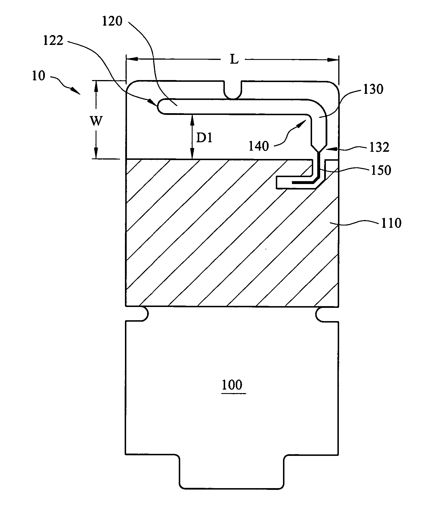
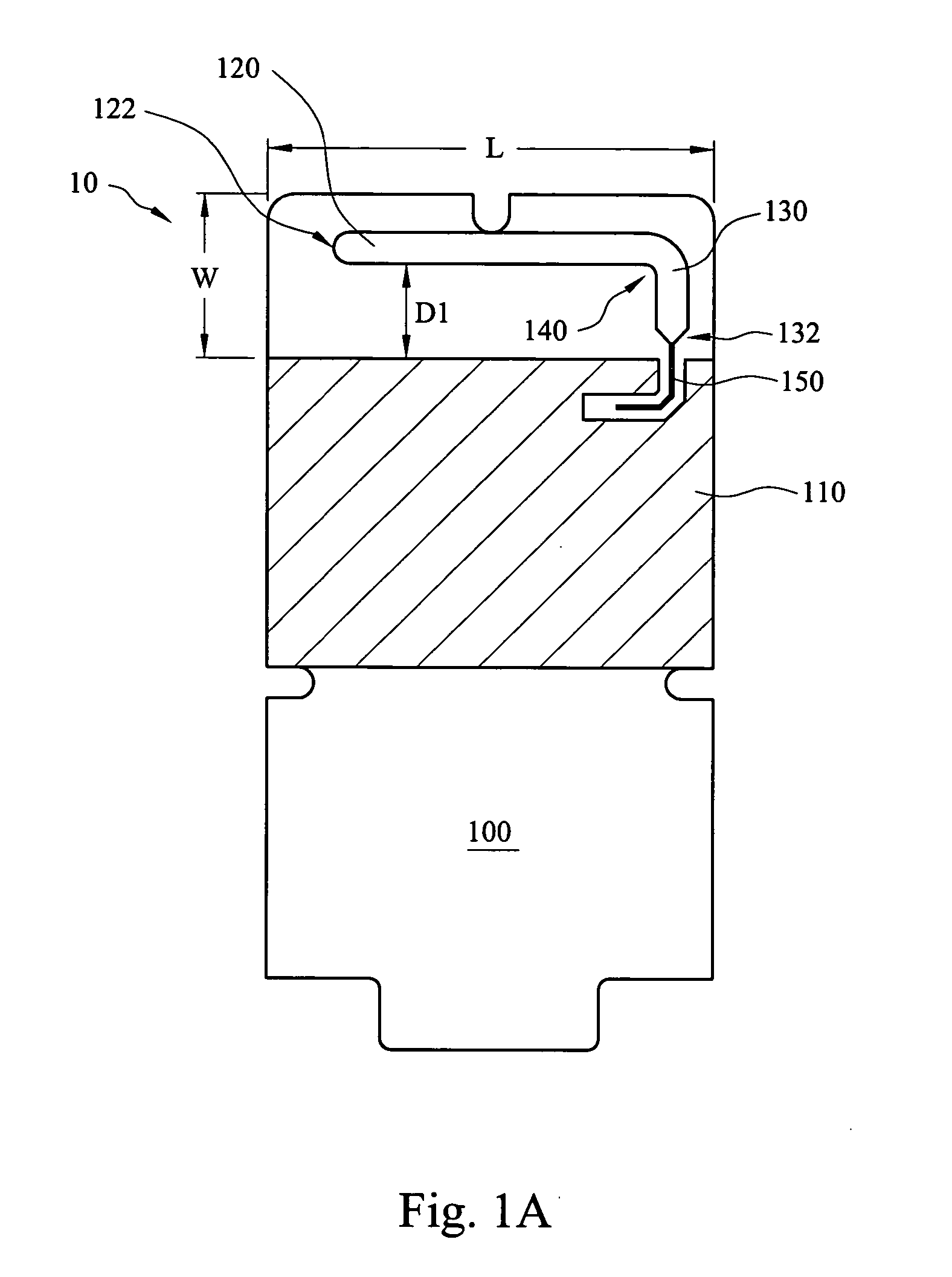
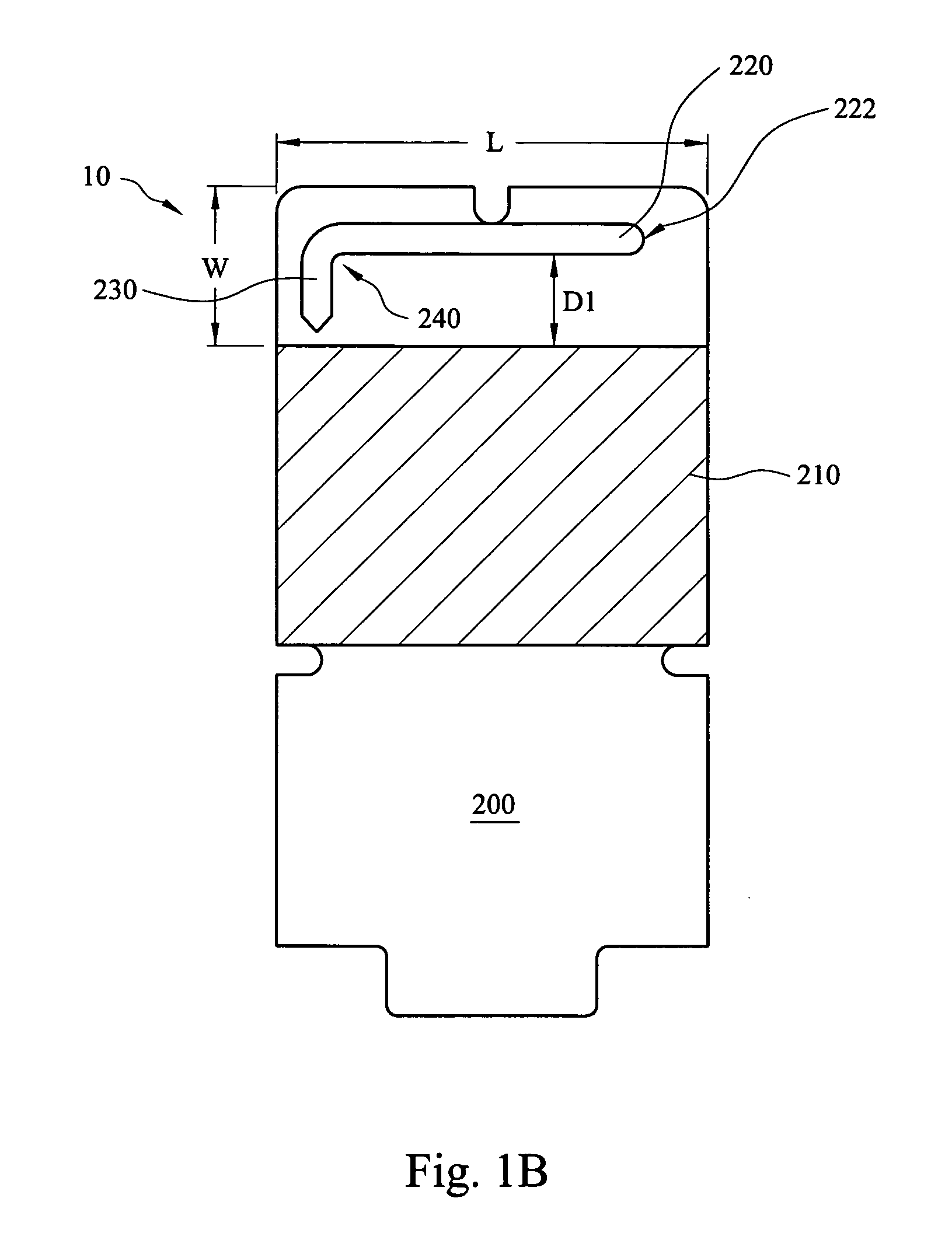
[0020] Referring to FIGS. 1A and 1B, FIG. 1A and FIG. 1B are schematic top and views showing a monopole antenna according to a first preferred embodiment of the present invention. The monopole antenna of the present invention is basically composed of two substantially L-shaped conductors (first and second substantially L-shaped conductors; not labeled) respectively formed on two opposite surfaces (a first planar surface 100 and a second planar surface 200) of a base board 10, wherein the base board 10 can be such as a printed circuit board made of BT (bismaleimide-triazine) resin or FR4 fiberglass reinforced epoxy resin, and the first and second substantially L-shaped conductors can be mirror-reflected to each other.

[0021] The first substantially L-shaped conductor is formed on the first planar surface 100, and is composed of a first main radiating strip 120 and a first extension radiating strip 130. The first extension radiating strip 130 is perpendicularly connected to the first ...


PUM


Abstract

A monopole antenna is disclosed. The monopole antenna comprises a base board, a first substantially L-shaped conductor, a first ground plane, a second substantially L-shaped conductor, a second ground plane and a feeding strip, and the monopole antenna further has a plurality of evenly-distributed through holes penetrating the base board from the first substantially L-shaped conductor to the second substantially L-shaped conductor. When the monopole antenna is operated at about 2.4-2.5 GHz, good radiation patterns and antenna gain are obtained for being applicable to IEEE802.11b / g specifications.

Description

FIELD OF THE INVENTION [0001] The present invention relates to a monopole antenna, and more particularly, to the monopole antenna with capacitance loaded. BACKGROUND OF THE INVENTION [0002] With the advancement of communication technologies, the applications using communication technologies have also increased significantly, thus making the related products more diversified. Especially, consumers have more demands on advanced functions from communication applications, so that many communication applications with different designs and functions have been continuously appearing in the market, wherein the computer network products with wireless communication functions are the main streams recently. Moreover, with integrated circuit (IC) technologies getting matured, the size of product has been gradually developed toward smallness, thinness, shortness and lightness. [0003] An antenna in the communication products is an element mainly used for radiating or receiving signals, and the ant...

Claims


Application Information

Patent Timeline
Patent Type & Authority Applications(United States)
IPC IPC(8): H01Q1/38
CPCH01Q9/42H01Q1/38
Inventor CHAO, WEN-SHIN
Owner ARCADYAN
Why Eureka
Try Eureka