Offset Planar Coil Coaxial Surge Suppressor

a planar coil and coaxial cable technology, applied in the direction of overvoltage protection resistors, emergency protective arrangements for limiting excess voltage/current, coupling device connections, etc., can solve the problems of large enclosure requirements and high cos

Active Publication Date: 2007-03-08
COMMSCOPE TECH LLC
View PDF21 Cites 32 Cited by
  • Summary
  • Abstract
  • Description
  • Claims
  • Application Information

AI Technical Summary

Problems solved by technology

To enclose the planar coil, the required enclosure is relatively large and expensive.

Method used


Image

  • Offset Planar Coil Coaxial Surge Suppressor
  • Offset Planar Coil Coaxial Surge Suppressor
  • Offset Planar Coil Coaxial Surge Suppressor

Examples


Embodiment Construction

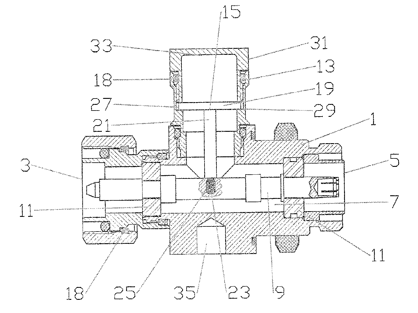
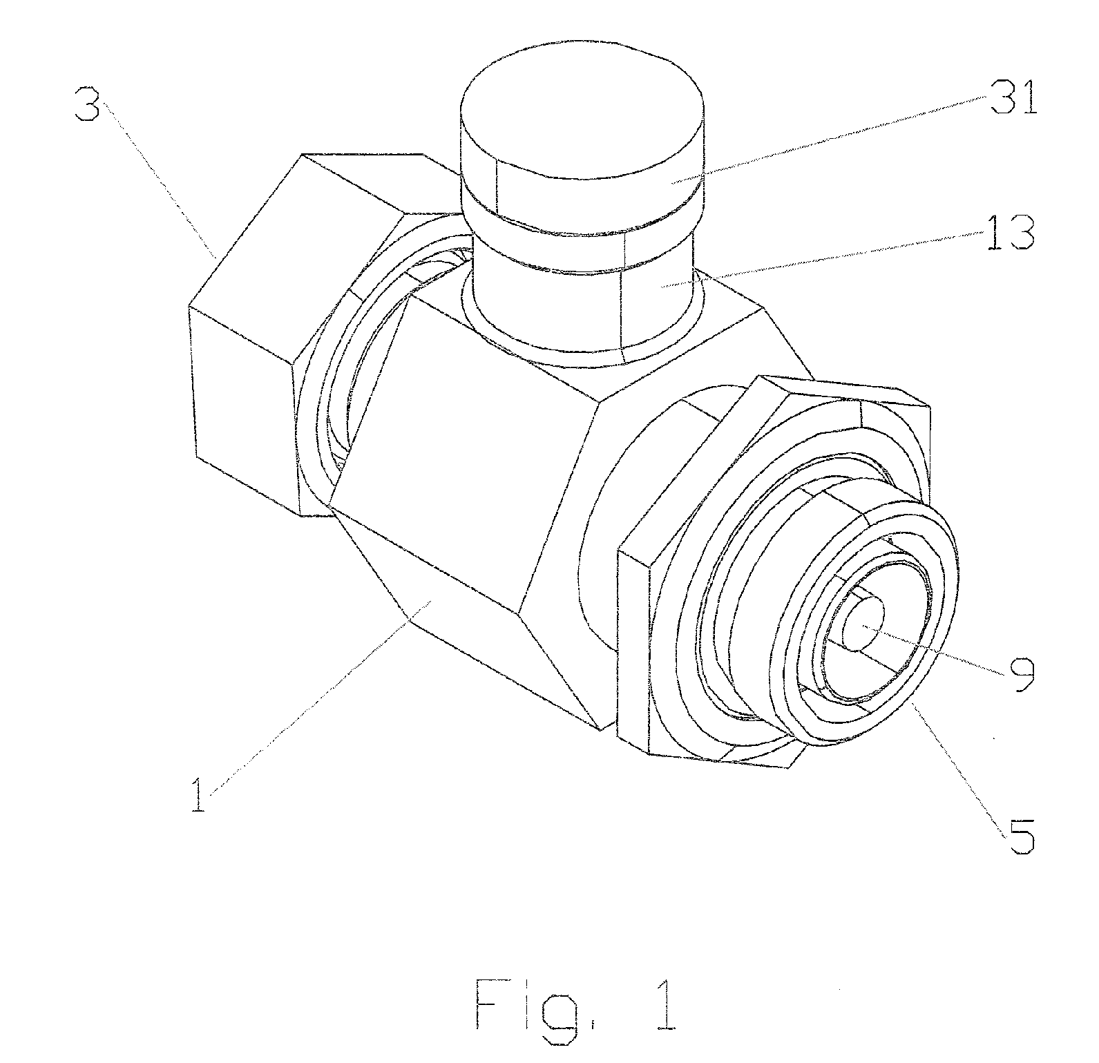
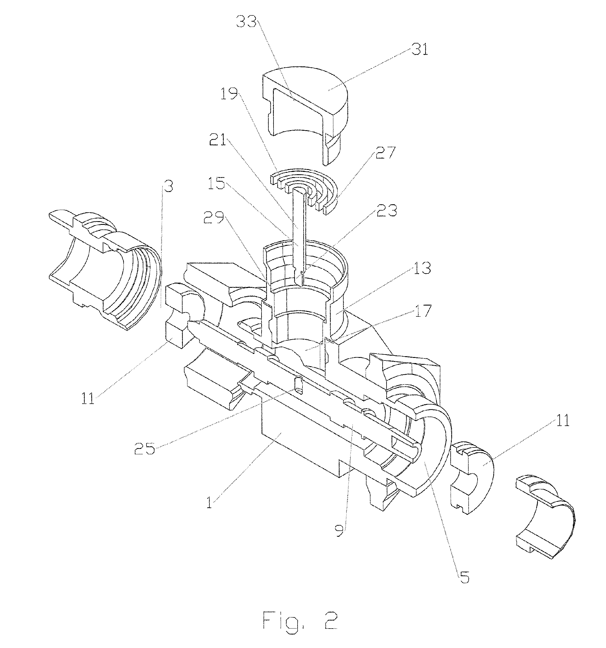
[0020] A first exemplary embodiment of the invention is described with reference to FIGS. 1-5.

[0021] The surge suppressor body 1 may be formed as an in-line assembly dimensioned for a desired co-axial cable or transmission line with a first connection end 3 and a second connection end 5 adapted to couple with a cable outer conductor of a co-axial cable or other equipment at either end via connection interface(s). Although the embodiments herein are demonstrated with 7-16 DIN connection interface(s), one skilled in the art will recognize that any desired standardized or proprietary connection interface may be applied. The body 1 has a bore 7 in which an inner conductor 9 is positioned, also extending between the first connection end 3 and the second connection end 5 to similarly couple with a cable inner conductor or other equipment. The inner conductor 9 may be positioned coaxial within the bore 7 and isolated from the body 1 by one or more insulator(s) 11. The inner conductor 9 ma...


PUM


Abstract

An in-line surge suppressor assembly having a body with a side aperture and an inner conductor positioned coaxial within a bore of the body. An insert having a planar inductor coil with a post extending from an origin point of the planar inductor coil is positioned with the post passing through the side aperture and coupled to the inner conductor at a distal end. An outer rim of the planar inductor coil is electrically coupled to the body.

Description

BACKGROUND [0001] 1. Field of the Invention [0002] The invention generally relates to surge protection of coaxial cables and transmission lines. More particularly, the invention relates to a planar coil surge suppressor insert and related compact surge protector housing for use in-line with a coaxial cable or transmission line, configurable for a range of different frequency bands. [0003] Description of Related Art [0004] Electrical cables, for example coaxial transmission lines of antenna towers, are equipped with surge suppression equipment to provide an electrical path to ground for diversion of electrical current surges resulting from, for example, static discharge and or lightning strikes. [0005] Prior coaxial suppression equipment typically incorporated a frequency selective shorting element between the inner and outer conductors dimensioned to be approximately one quarter of the frequency band center frequency in length, known as a quarter wavelength stub. Therefore, frequenc...

Claims


Application Information

Patent Timeline
Patent Type & Authority Applications(United States)
IPC IPC(8): H02H9/06
CPCH01R24/48H01T4/08H01R2103/00H01R24/547
Inventor HARWATH, FRANK
Owner COMMSCOPE TECH LLC
Why Eureka
Try Eureka