Advanced heat sinks and thermal spreaders

a heat sink and spreader technology, applied in the direction of lighting, heating apparatus, instruments, etc., can solve the problems of increasing weight, increasing cost, and poor heat transfer rate from heat source surfaces to surrounding air

Inactive Publication Date: 2007-03-08
GENERAL ELECTRIC CO
View PDF36 Cites 240 Cited by
  • Summary
  • Abstract
  • Description
  • Claims
  • Application Information

AI Technical Summary

Benefits of technology

[0011] The invention further relates to a method for constructing a fin for use in a heat sink, by cleaving at least a graphite layer having a thickness of less than 0.1 from a sheet of gra

Problems solved by technology

The heat transfer rate from heat source surfaces directly to the surrounding air is typically poor.
101 W/m·K), but is more expensive.
Copper is also denser, adding weight to the heat sink and making the heat

Method used


Image

  • Advanced heat sinks and thermal spreaders
  • Advanced heat sinks and thermal spreaders
  • Advanced heat sinks and thermal spreaders

Examples


example 1

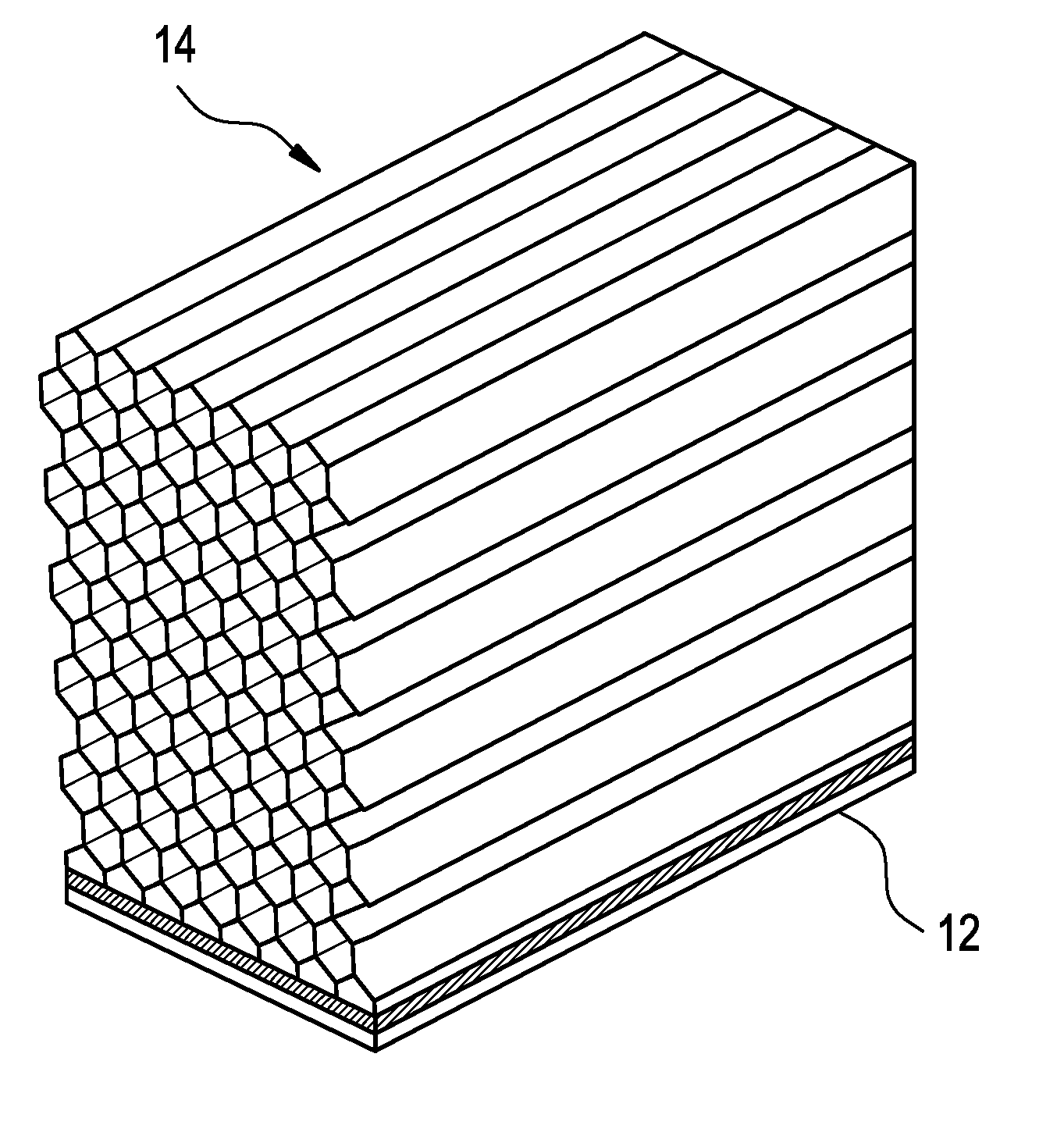
[0085] A thermal pyrolytic graphite (TPG) sheet commercially available from General Electric Company is secured against a fat surface. A metal foil backed with a highly conductive adhesive tape, die cut to slightly overlap the TPG sheet, is pressed against the TPG Sheet. Metal foil tapes are commercially available from sources including Chomerics as CHO-FOIL® or CHO-FOIL® EMI shielding tapes. The metal foil sheet is peeled off, inducing the cleaving of the top graphene layer(s) from the pyrolytic graphite surface, and for the cleaving to be affixed to the adhesive backing of the metal foil tape. After the top cleaving is cleaved off, the process is repeated to obtain the next graphite cleaving.

example 2

[0086] The bare (not laminated) graphite layer surfaces of the metal-foil backed graphite strips in Example 1 are brushed with Parylene C using a small paint brush for thickness of 0.10, 0.25, 0.50, 0.75 and 1.00 mil (thousandth of an inch). The results show that as the thickness of Parylene increases, the mechanical robustness of the ultra-thin heat sink of the invention increases with the gain in robustness falling off at about 0.50 mil.

example 3

[0087] A two part, silver load, B-staged adhesive system is applied onto the bare graphite layer surface of the metal-foil backed strips obtained in Example. The resulting thermal conductivity of the heat sink is at least 75% of an uncoated TPG product.


PUM

PropertyMeasurementUnit
Thicknessaaaaaaaaaa
Thicknessaaaaaaaaaa
Thicknessaaaaaaaaaa

Abstract

A heat sink assembly for an electronic device or a heat generating device(s) is constructed from an ultra-thin graphite layer. The ultra-thin graphite layer exhibits thermal conductivity which is anisotropic in nature and is greater than 500 W/m° C. in at least one plane and comprises at least a graphene layer. The ultra-thin graphite layer is structurally supported by a layer comprising at least one of a metal, a polymeric resin, a ceramic, and a mixture thereof, which is disposed on at least one surface of the graphite layer.

Description

CROSS-REFERENCE TO RELATED APPLICATIONS [0001] This application claims the benefits of U.S. Patent Appl. No. 60 / 743998 filed Mar. 30, 2006, which patent application is fully incorporated herein by reference. This application is also a continuation-in-part (CIP) of U.S. patent application Ser. No. 10 / 761,567, with a filing date of Jan. 21, 2004.FIELD OF THE INVENTION [0002] The present invention relates to a thermal management assembly including but not limited to a heat spreader, which can be used for transferring heat away from a heat source, e.g., to a heat sink; an assembly having the heat spreader in contact with the heat source, e.g., between the heat source and the heat sink; a heat sink for dissipating the heat. The invention also relates to methods of manufacturing a thermal management assembly. BACKGROUND OF THE INVENTION [0003] Advances in microelectronics technology have resulted in electronic devices which process signals and data at unprecedented high speeds. Electronic...

Claims


Application Information

Patent Timeline
IPC IPC(8): H05K7/20
CPCB32B18/00B32B2315/02H01L2924/0002C04B35/522C04B35/645C04B2235/9607C04B2237/363C04B2237/66C04B2237/704F28F3/02F28F3/022F28F3/025F28F13/18F28F21/02G06F1/20H01L23/367H01L23/3672H01L23/3677H01L23/373H01L23/3735H01L23/467C04B2237/086C04B2237/32C04B2237/82C04B2237/84H01L2924/00H05K7/20B82Y30/00
Inventor SAYIR, HALUKMEHMET, ARIKCOOPER, EVAN B.ICOZ, TUNCSCHAEPKENS, MARCLIU, XIANG
Owner GENERAL ELECTRIC CO
Why Eureka
Try Eureka