Optical disk device and integrated circuit used therein

a technology of optical disk and integrated circuit, which is applied in the field can solve the problems of difficult to separate the baseband readout signal and the high-order spectrum, and employ high-frequency modulation, and achieve the effects of effective restriction of line and other distortion spectrum components, improved readout signal quality of optical disk devices, and easy removal of distortion components

Inactive Publication Date: 2007-03-08
HITACHI CONSUMER ELECTRONICS CORP
View PDF10 Cites 24 Cited by
  • Summary
  • Abstract
  • Description
  • Claims
  • Application Information

AI Technical Summary

Benefits of technology

[0014] In order to resolve the abovementioned problems, the optical disk device according to the present invention has a means for converting a pulse readout signal into a continuous signal without losing its amplitude. Further, it has a means for performing sample and hold of the pulse readout signal's peak value for each cycle in synchronization with the HF signal. Further, it has a means for digitizing the aforementioned values that have been held. Further, it has a means for suppressing the line spectrum, which is a distortion component contained in the pulse readout signal spectrum. Further, it has a means for generating a high-frequency modulating signal in the laser drive current, completely independently of the channel clock.
[0015] As a means to convert a pulse readout signal to a continuous signal, a peak hold circuit may be used. By using a peak hold circuit, it is possible to effectively restrict line and other distortion spectrum components originating from the HF signal in the high-frequency spectrum of the pulse readout signal, making it easy to remove distortion components using a low-pass filter.
[0016] According to the present invention, the readout signal quality of an optical disk device improves dramatically. Further, it becomes easier to achieve both the high-frequency modulation conditions for laser noise reduction as well as high-speed readout.

Problems solved by technology

The standards for double speed readout assume a method for obtaining a continuous readout signal from the pulse readout signal, as described in the section entitled “BACKGROUND OF THE INVENTION.” However, in the case of further increases to the speed factor, at least the following two problems will arise in a system using this method.
The second is that due to the expansion of the readout signal bandwidth, the HF frequency and readout signal bandwidth will become closer together, making it difficult to separate the baseband readout signal and the high-order spectrum.
Of these problems, the first is one that will always be faced when increasing the speed factor, whatever the method.
The second problem arises in a system employing high-frequency modulation.

Method used


Image

  • Optical disk device and integrated circuit used therein
  • Optical disk device and integrated circuit used therein
  • Optical disk device and integrated circuit used therein

Examples


first embodiment

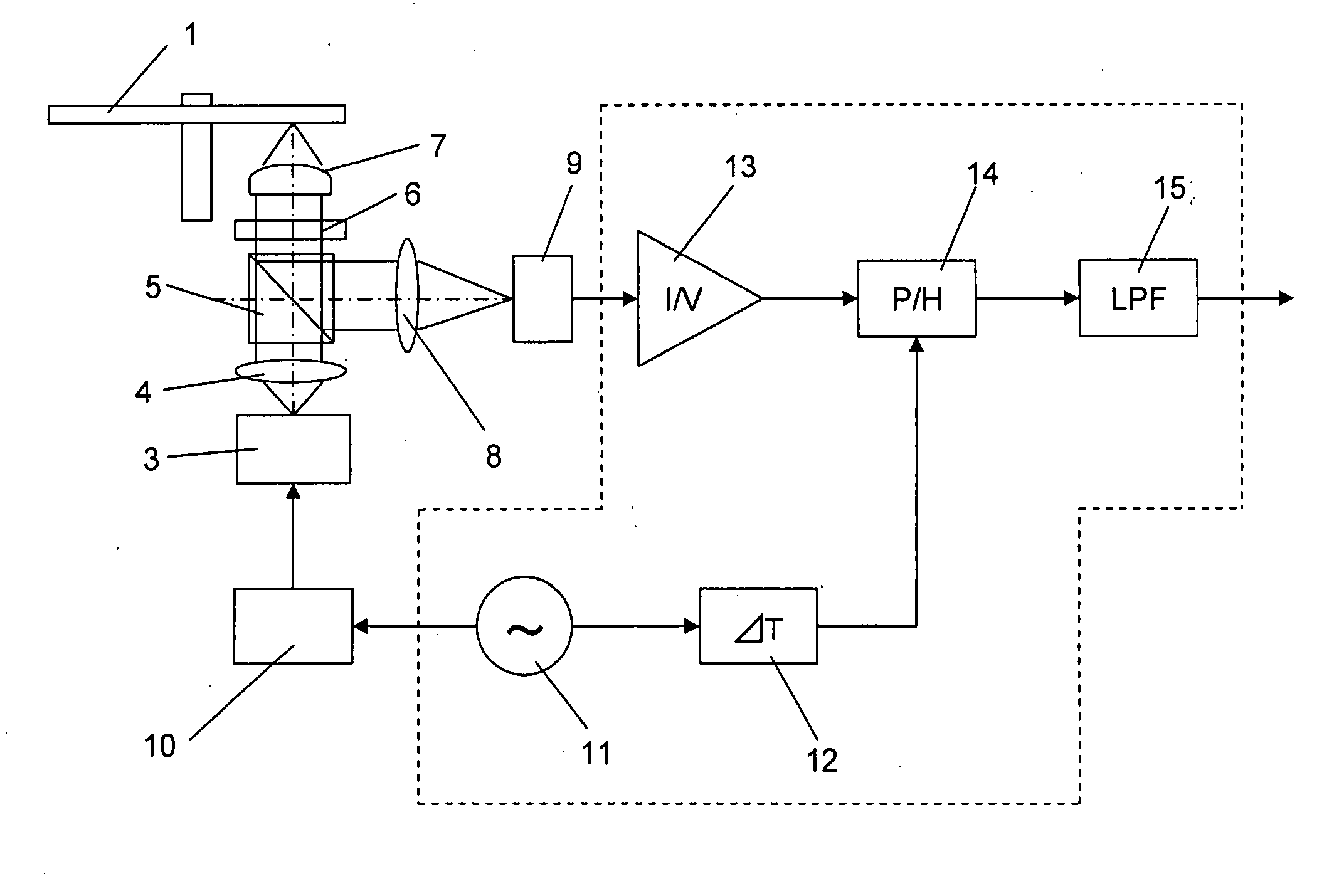
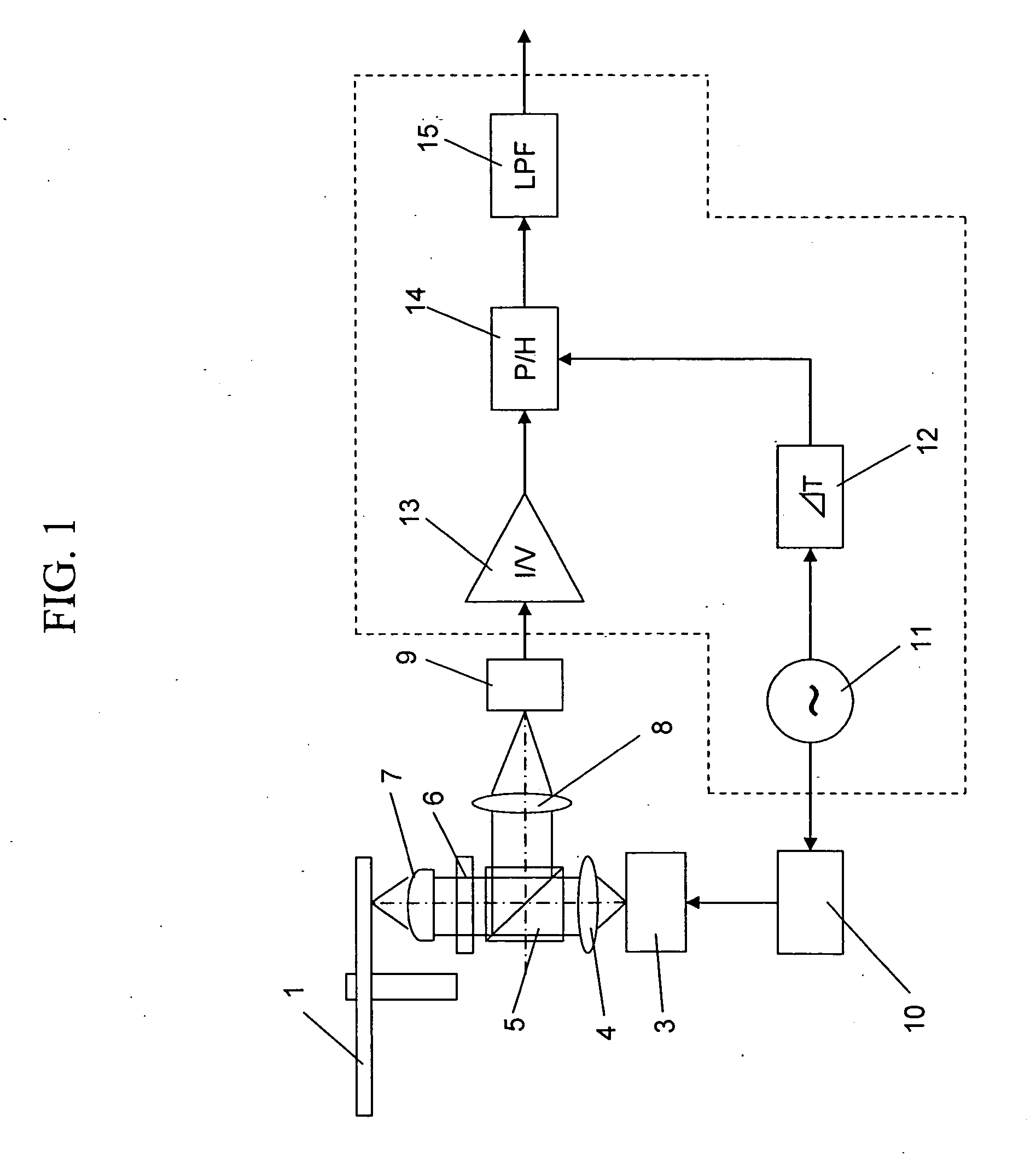
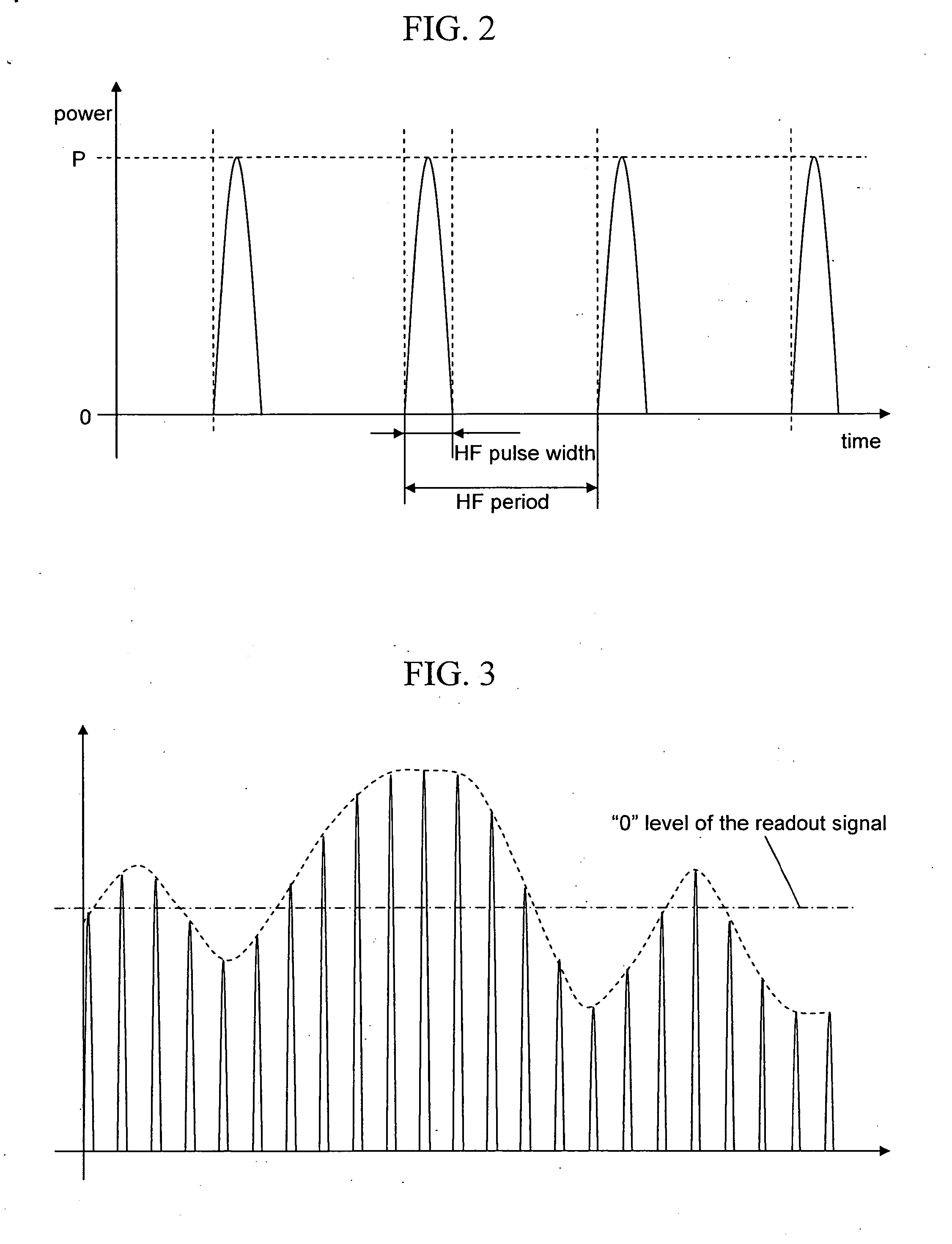
[0028]FIG. 1 is a view showing a frame format of one example of an optical disk device according to the present invention. Note that in this figure, aspects not necessary for the following explanation have been omitted, and mainly the pickup is described. The present embodiment employs a peak hold circuit 14 as a means for converting the pulse readout signal to a continuous waveform. Note that the pulse readout signal is composed of a pulse train that is discrete in time, and the essences of the signal are in the time and the peak value of each pulse. In contrast, the continuous signal referred to herein is meant to be composed of not only components essentially discrete in time (pulses) like the pulse readout signal, and has a broader meaning than the ordinary meaning of a continuous signal. Therefore, it includes cases when the signal amplitude suddenly becomes 0 in a short time period.

[0029] The high-frequency modulating signal (HF signal) is generated in an HF oscillator 11 and...

second embodiment

[0040]FIG. 9A is the peak hold circuit output spectrum when the present invention is applied to a 12× readout BD. From the perspective of laser noise, it was assumed that the HF frequency could not be moved very far from around 400 MHz. Accordingly, although the channel clock frequency was 792 MHz, and the 2 T frequency was 198 MHz, the HF frequency was set at 528 MHz. In this way, according to the present invention, it is possible to set the HF frequency lower than the channel clock frequency. Considering the two factors; the possibility of achieving latter stage low-pass filter properties and the overlapping of the signal spectrum below the optical cutoff frequency, we used a 6th-order Bessel low-pass filter with a cutoff frequency of 250 MHz for the final stage low-pass filter. FIG. 9B shows the spectrum after passing through the low-pass filter. According to this, the distortion component spectrum closest to the readout signal bandwidth is approximately 40 dB lower than the read...

third embodiment

[0042]FIG. 10 is a view showing a frame format of another example of a disk drive according to the present invention. In this embodiment, each pulse of the pulse readout signal is directly converted into digital data. The process by which the HF laser pulse is converted into an electronic signal is the same as explained in the first embodiment, so explanation is omitted here. The output of the current amplifier 13 is inputted into the peak hold circuit 14 after passing through a variable gain amplifier 32. The gain of the variable gain amplifier 32 is indicated based on the readout signal amplitude detected in the signal processing system.

[0043] Usually, with an analog to digital converter, which converts analog signals to digital signals, since the subject is a continuous signal, first, amplitude information is held for a set period of time in the sample hold circuit, and then the values held for that time are converted into digital data. The mechanism that performs the latter pro...


PUM

PropertyMeasurementUnit
frequencyaaaaaaaaaa
HF frequencyaaaaaaaaaa

Abstract

This invention involves irradiating an optical disk with laser light, pulse-driven by a high-frequency signal from an HF oscillator, and converting the output of a photo-detector that receives laser light reflected from the optical disk into an electronic pulse readout signal using a current amplifier. The pulse readout signal is converted into a temporally continuous readout signal by a peak hold circuit. The invention solves the problems of SNR deterioration of the readout signal and the difficulty of removing the impact of high-frequency modulation accompanying the increase in the readout speed factor in optical disk devices.

Description

CLAIM OF PRIORITY [0001] The present application claims priority from Japanese application JP 2005-260540 filed on Sep. 8, 2005, the content of which is hereby incorporated by reference into this application. FIELD OF THE INVENTION [0002] The present invention relates to an optical disk device, and more specifically to a circuit for performing readout of information from an optical disk. BACKGROUND OF THE INVENTION [0003] Most current optical disk devices such as DVDs employ high-frequency modulation to restrict noise generated by the laser diode, which is used as the light source thereof. This strategy is well known by persons skilled in the art, and therefore, the following description contains only essential features and not details. [0004] When high-frequency modulation is used, the laser performs pulse emission. In other words, the emission waveform repeatedly alternates between emission and turned off states, as shown in FIG. 2. In this case, the laser pulse interval (frequenc...

Claims


Application Information

Patent Timeline
Patent Type & Authority Applications(United States)
IPC IPC(8): G11B20/10
CPCG11B7/005
Inventor KIKUGAWA, ATSUSHIMINEMURA, HIROYUKI
Owner HITACHI CONSUMER ELECTRONICS CORP
Why Eureka
Try Eureka