Systems and methods for reducing rain effects in images

Inactive Publication Date: 2007-03-08
THE TRUSTEES OF COLUMBIA UNIV IN THE CITY OF NEW YORK
View PDF13 Cites 22 Cited by
  • Summary
  • Abstract
  • Description
  • Claims
  • Application Information

AI Technical Summary

Benefits of technology

[0010] We have developed an analytical model for the effects of dynamic weather on acquired images based on the intensity fluctuations caused by such weather. We have also developed a method of adjusting camera settings to reduce the visibility of rain with minimal degradation of the acquired image. This method uses one or more inputs from a user to retrieve settings for an image acquisition device from a data repository. These settings are then used to adjust corresponding camera settings. The input from a user can be, at least, the heaviness of the rainfall, the motion of objects in the scene, the distance of an object to be acquired from the camera, or the near and far distance of the scene. Camera settings that can be adjusted are, at least, the exposure time, the F-number, the focal plane, or the zoom. Although post processing is preferably not required to reduce the visibility of dynamic weather, such as ra

Problems solved by technology

Although post processing is preferably not required to reduce the visibility of dynamic weather, such as rain, when the present invention is implemented,

Method used


Image

  • Systems and methods for reducing rain effects in images
  • Systems and methods for reducing rain effects in images
  • Systems and methods for reducing rain effects in images

Examples


first embodiment

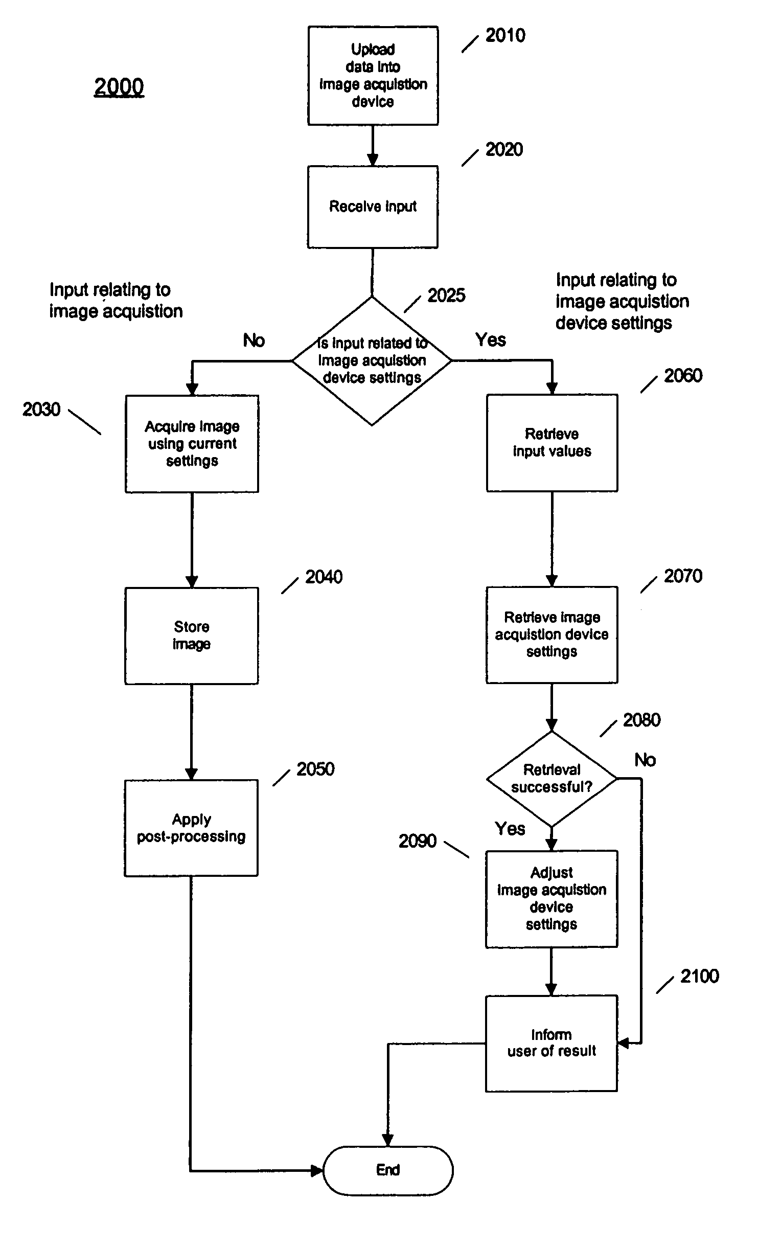
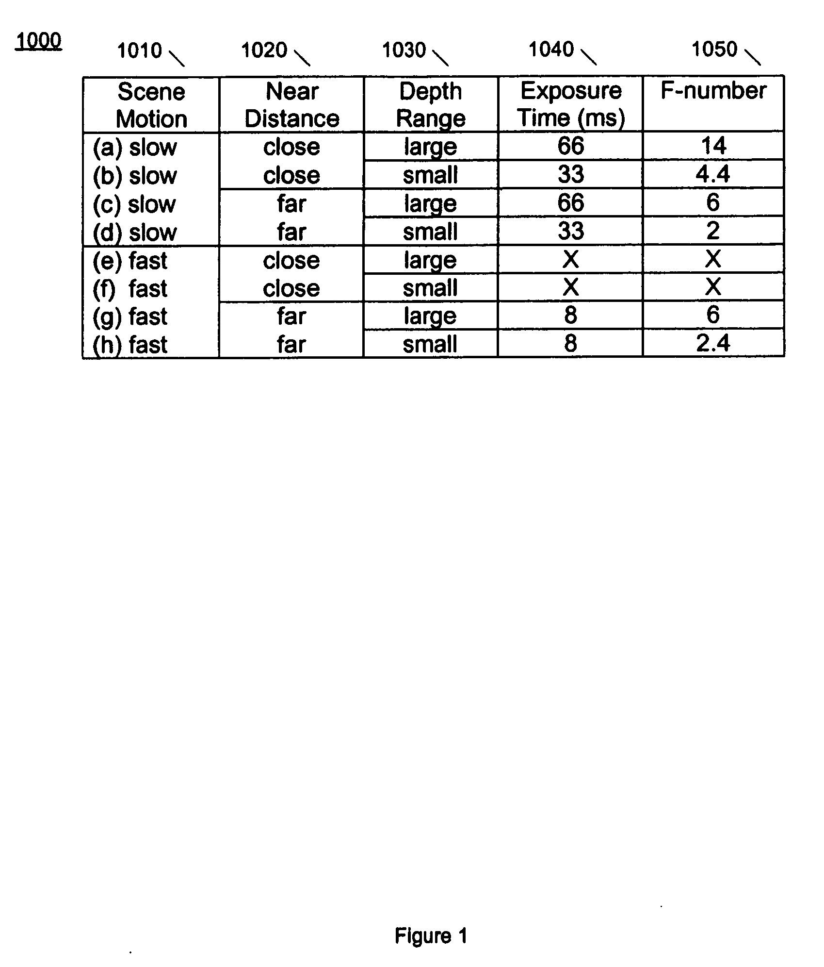
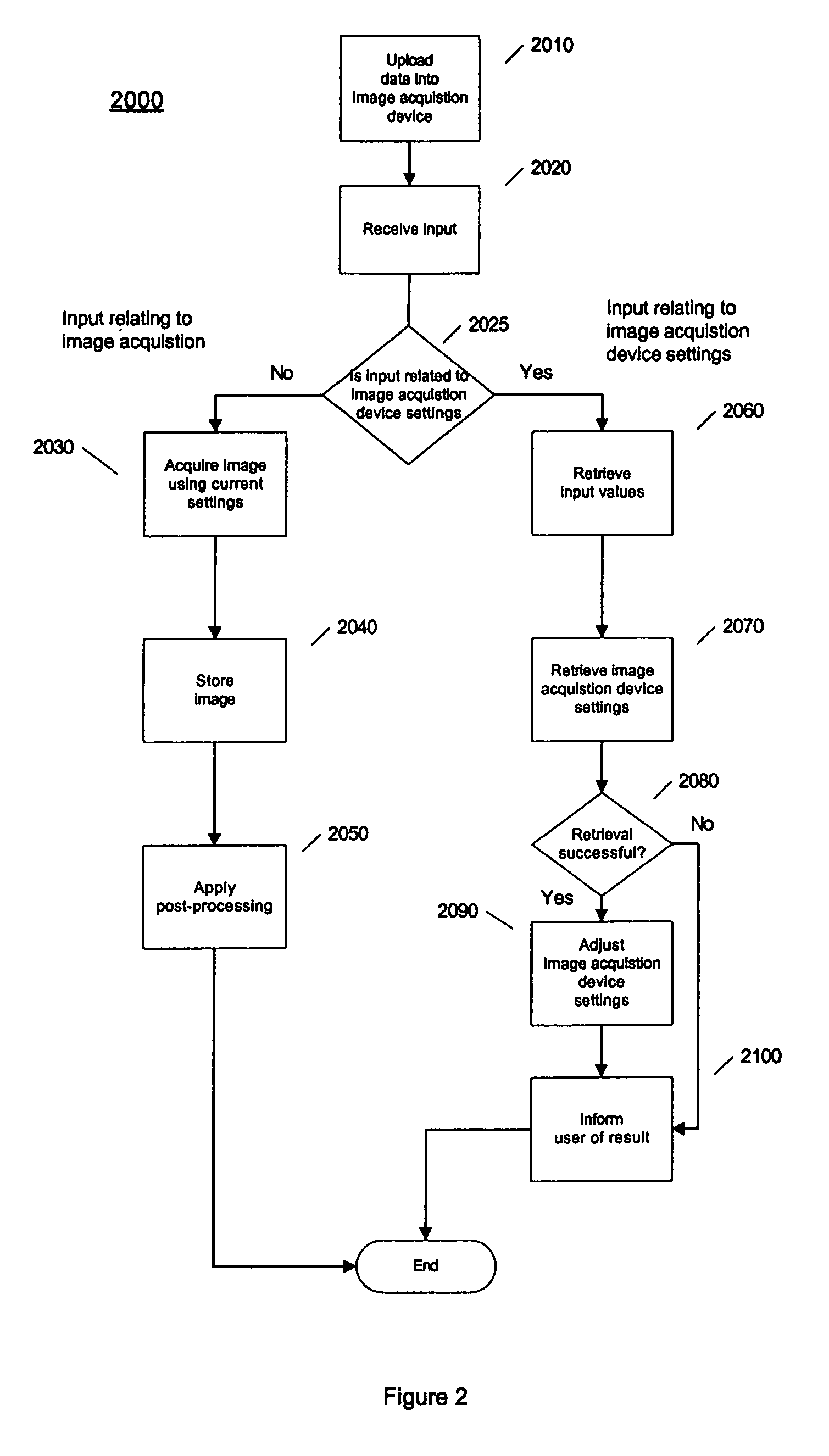
[0030]FIG. 2, is an exemplary flow diagram of the invention which shows details for the process of adjusting camera settings 2000, using a table like the one described above with reference to FIG. 1. Overall, the system receives input from a user, uses the input to retrieve camera setting that will reduce the visibility of rain based on the user's input, and then adjusts the camera setting according to the retrieved settings.

[0031] At block 2010, data corresponding to that shown in FIG. 1 is uploaded into the camera. This upload may be done through any well known means such as a serial cable, universal serial bus connection, a wireless connection, or a memory card. Alternatively, this data may be installed when the camera is manufactured, and may contain settings considered “optimal” by the camera manufacturer. These settings may be stored in any type of memory, although a non-volatile type of memory, such as EEPROM or flash memory, may be preferred for reduced power consumption.

[0...

second embodiment

[0041]FIG. 3 is an exemplary flow diagram of the invention which shows details of measuring the rain rate. This embodiment of the invention is based on using the analytical model described above in a way that is used to find camera settings that enhance the visibility of rain, instead of reduce the visibility of rain. By enhancing the visibility of rain, the size and number of raindrops can be measured, leading to a measurement of the rain rate.

[0042] The method starts at block 3010, where the camera (image acquisition device) settings are adjusted to enhance the visibility of rain. The distance of the focal plane is set to less than (2*f*amin) to make the smallest rain drop size visible, where amin is the minimum size of a raindrop. The F-number is set to a small number, and the depth of field is set to a small range.

[0043] At block 3020, an image is acquired using the settings entered at block 3010. The acquired frame can be analyzed immediately and / or analyzed concurrently with ...


PUM


Abstract

Systems and methods for reducing the visibility of rain in acquired images are provided. One or more inputs relating the scene desired to be acquired by the user are used to retrieve camera settings that will reduce the visibility of rain in acquired images. Additionally, features relating to the scene may be automatically determined and used alone, or in combination with user inputs, to retrieve camera settings. The acquired images may be part of a video. Another feature of the invention is its use as a rain gauge. The camera settings are adjusted to enhance the visibility of rain, then one ore more images are acquired and analyzed for the amount and size of raindrops. From this analysis the rain rate can be determined.

Description

CROSS-REFERENCE TO RELATED APPLICATIONS [0001] This application claims the benefit under 35 U.S.C. 119(e) of U.S. Provisional Patent Application No. 60 / 662,191, filed on Mar. 16, 2005, entitled Methods for Eliminating Rain Effects in Video, which is hereby incorporated by reference herein in its entirety.STATEMENT REGARDING FEDERALLY SPONSORED RESEARCH OR DEVELOPMENT [0002] The invention disclosed herein was made with U.S. Government support from the National Science Foundation (Award No. IIS-04-12759) and the Office of Naval Research (Award No. N00014-05-1-0188). Accordingly, the U.S. Government may have certain rights in this invention.FIELD OF THE INVENTION [0003] The present invention relates to the field of computer vision and more specifically to acquiring images in a way that reduces the need for post processing of images. BACKGROUND OF THE INVENTION [0004] Images acquired by both still and video cameras (or any image acquisition device) can be affected by many factors. This ...

Claims


Application Information

Patent Timeline
IPC IPC(8): G03B17/00G01N21/00
CPCG01W1/14G06K9/346H04N5/232G06T2207/30242G06T7/0002G06V10/273H04N23/633
Inventor GARG, KSHITIZNAYAR, SHREE K.
Owner THE TRUSTEES OF COLUMBIA UNIV IN THE CITY OF NEW YORK
Why Eureka
Try Eureka