
Microwave plasma processing method, microwave plasma processing apparatus, and its plasma head

a plasma processing and microwave technology, applied in the field of microwave plasma processing methods, microwave processing apparatuses and their plasmaheads, can solve the problems of standing wave non-uniformity, incomplete processing of gas flow and gas shielding, non-uniform plasma density, etc., to prevent the leakage of gas, improve the film deposition rate, and high accuracy

Inactive Publication Date: 2007-03-08
FUTURE VISION +1
View PDF4 Cites 22 Cited by
  • Summary
  • Abstract
  • Description
  • Claims
  • Application Information

AI Technical Summary

Benefits of technology

[0013] Further, according to the microwave plasma processing method, the microwave plasma processing apparatus and the plasma head of the present invention, a uniforming line is provided on the plasma head under similar processing conditions, and the uniforming line is made of a material with high dielectric constant. Also, the uniforming line is made of quartz, and its end portion is extended by ¼λ. Also, an electromagnetic wave absorbing material with high dielectric loss is attached on end portion of the uniforming line to reduce the standing wave on the plasma head where the symbol λ represents free space wavelength of quartz.
[0015] Further, according to the microwave plasma processing method, the microwave plasma processing apparatus and the plasma head of the present invention, a feeding pipe for feeding a shield gas into the plasma head is connected, and by a buffer plate the shield gas is uniformly supplied into the plasma processing chamber downstream of the shield gas feeding pipe. Also, a buffer plate for carrying out uniform exhaust of the gas is provided on exhaust side. A pressure P1 in the plasma processing chamber is set to a value lower than a pressure P3 on the outermost periphery of the plasma head, and the pressure P3 is set to a value lower than a pressure P2 near the buffer plate for performing uniform exhaust, thus preventing the leakage of the gas from the plasma head.
[0016] According to the microwave plasma processing method, the microwave plasma processing apparatus and the plasma head of the present invention, linear high-density plasma is generated from the plasma head by using a high-density microwave source. As a result, it is possible to perform continuous CVD processing with high accuracy. Different types of plasma sources are aligned in transporting direction of the substrate to be processed by film-deposition processing. As a result, different types of continuous film deposition can be carried out.
[0017] Further, according to the microwave plasma processing method, the microwave plasma processing apparatus and the plasma head, and a uniforming line of the plasma head of the present invention, by setting optimal condition of the basic dimensions and by eliminating the standing wave, more uniform microwave can be emitted through the slit of the plasma head. Also, homogeneity of the film deposition gas can be maintained because of down-flowing and side-flowing of the gas, and this contributes to the improvement of the film deposition rate.
[0018] Also, remarkable effects can be provided for gas shielding of the film deposition gas with very high accuracy.

Problems solved by technology

Although different types of processing can be continuously carried out by the conventional type microwave plasma CVD method and apparatus as described above, there have been problems in: non-uniformity of microwave at the microwave feeding unit of the plasma head, incompleteness of processing of gas flow and gas shielding, non-uniformity of plasma density due to the standing wave, abnormal discharge at slots of the plasma head, etc.

Method used


Image

  • Microwave plasma processing method, microwave plasma processing apparatus, and its plasma head
  • Microwave plasma processing method, microwave plasma processing apparatus, and its plasma head
  • Microwave plasma processing method, microwave plasma processing apparatus, and its plasma head

Examples


Embodiment Construction

[0033] Detailed description will be given below on embodiments of a microwave plasma processing method, a microwave plasma processing apparatus and a plasma head according to the present invention referring to the attached drawings.

[Microwave Plasma CVD Apparatus]

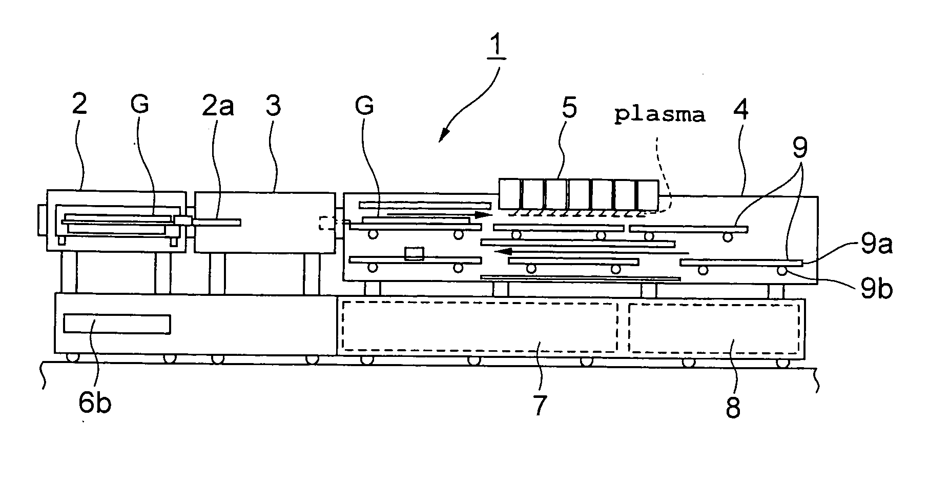
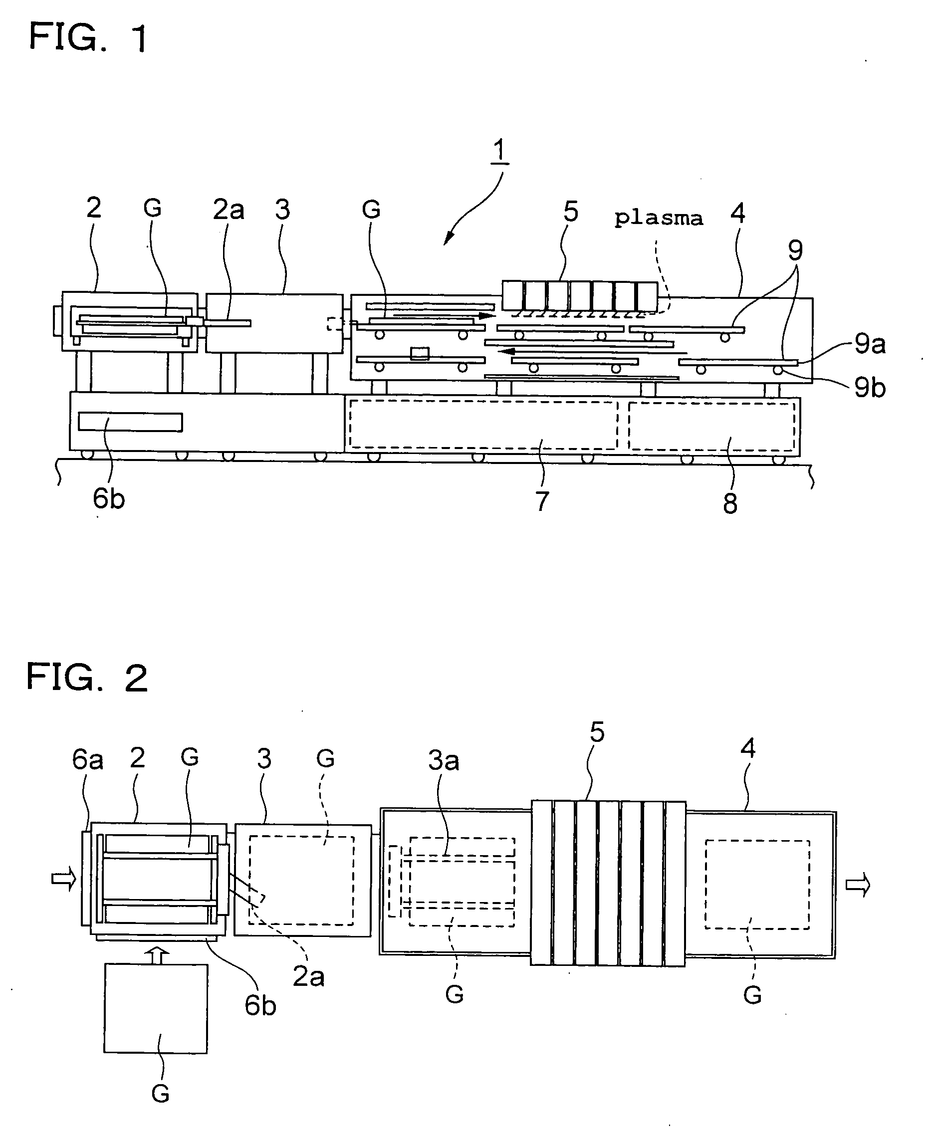
[0034] First, as shown in FIG. 1 and FIG. 2, in a microwave plasma CVD apparatus 1 in an embodiment of the present invention (hereinafter referred as “CVD apparatus of the present invention”), a substrate G (e.g. a glass substrate) is brought into a load-lock module 2 from a platform 6a or 6b and is sent to a process module 4 by a robot arm 3a via a transfer module 3 by a transport arm 2a. Then, linear plasma of high density is generated by a plasma head5. Under the presence of the linear plasma, processing surface of the substrate (object to be processed) G is maintained at horizontal position with respect to the linear plasma, and plasma CVD processing is continuously performed on in-line basis on the substrate G. In pa...


PUM

PropertyMeasurementUnit
thicknessaaaaaaaaaa
pressureaaaaaaaaaa
pressureaaaaaaaaaa

Abstract

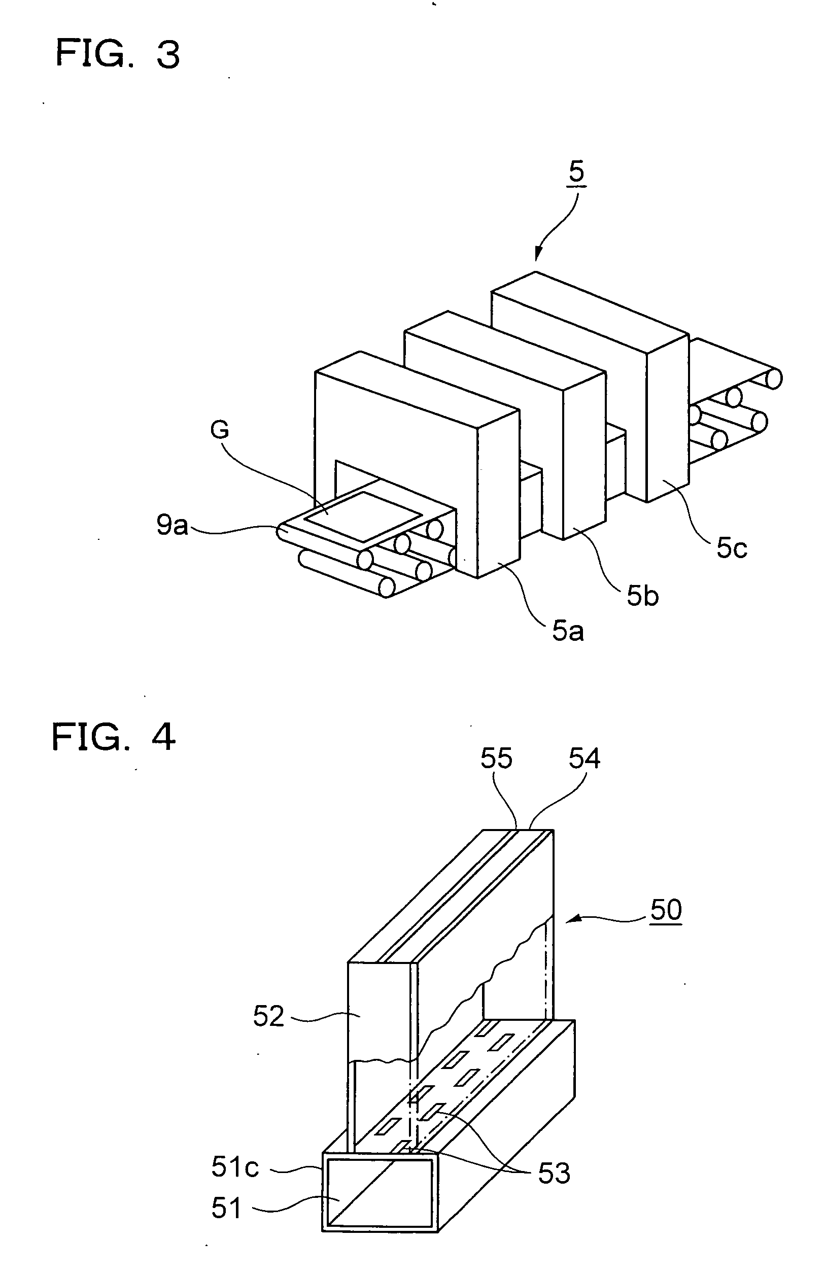
A microwave plasma processing method and, in which a linear plasma is produced by means of a microwave, and an object to be processed is subjected to processing under atmospheric pressure or under a pressure near atmospheric pressure when the object is moved, while a surface of the object is maintained at a horizontal position with respect to the linear plasma. A plasma head has an H-plane slot antenna, and slots are arranged alternately on both sides of a centerline of a waveguide at a pitch of λg / 2 (λg: wavelength of the microwave with the waveguide). A uniforming line having a distance of n·λg / 2 from the slots to an emission end of the plasma head is provided (n: an integral number).

Description

FIELD OF THE INVENTION [0001] The present invention relates to a microwave plasma processing method, a microwave processing apparatus and its plasma-head, used for the microwave plasma processing of a large type glass substrate for flat panel display (FPD) or a substrate such as a semiconductor wafer. BACKGROUND ART [0002] For instance, in a microwave plasma CVD processing apparatus for processing a large type glass substrate for FPD or a substrate such as a semiconductor wafer, it has been practiced in the past in such manner that a batch processing of the sheet-by-sheet type has been carried out and the substrates to be processed by plasma CVD processing has been passed through a load-lock chamber kept under vacuum condition and the substrates have been brought into or out of a processing chamber maintained similarly under a predetermined vacuum condition. As a result, each time the substrates were brought into or out of the processing chamber, the processing chamber had to be eva...

Claims


Application Information

Patent Timeline
Patent Type & Authority Applications(United States)
IPC IPC(8): H05H1/24C23C16/00C23C16/511H01L21/205H01L21/302H01L21/306H05H1/46
CPCH01L21/306H05H1/46H05H1/24H05H1/4622H05H1/463
Inventor OHMI, TADAHIROHIRAYAMA, MASAKIHORIGUCHI, TAKAHIROHIROE, AKIHIKOKITAMURA, MASAYUKI
Owner FUTURE VISION
Learn More