Probe for a coordinate measuring machine

a technology of coordinate measuring machine and probe, which is applied in the direction of instruments, applications, diagnostic recording/measuring, etc., can solve the problems of measuring inaccuracy, feeler pin itself vibrating when the probe is moved, etc., and achieves compact design, negative effect, and high damping effect.

Active Publication Date: 2007-03-15
CARL ZEISS IND MESSTECHN GMBH
View PDF18 Cites 11 Cited by
  • Summary
  • Abstract
  • Description
  • Claims
  • Application Information

AI Technical Summary

Benefits of technology

[0025] In other words, the first and second conductor elements (and possibly further conductor elements which can be integrally connected to one another or be implemented separately) are arranged such that they are distributed at a radial distance from the moveable second part on the outer circumference of the latter. Said conductor elements accordingly have different circumferential positions in relation to the moveable second part. If the number of conductor elements is limited to two, these are preferably circumferentially offset by 90° with respect to one another, and this allows damping of the moveable part in two coordinate directions with a small number of components. In an alternative, likewise preferred refinement, the two conductor elements are circumferentially offset by 180° with respect to one another in order to obtain a high damping effect in one coordinate direction and also a symmetrical distribution of weight.
[0026] The preferred refinement leads to a very compact design. This also allows vibrations transverse to the orientation of the feeler pin, i.e. typically vibrations in the x- and y-directions, to be damped in a very efficient manner. Vibrations of this type have a particularly negative effect when the probe is moving.

Problems solved by technology

However, mounting the feeler pin such that it can move may lead to the feeler pin itself vibrating when the probe is moved.
The natural vibrations cause disturbances when the probe approaches the object and may lead to measurement inaccuracies.

Method used


Image

  • Probe for a coordinate measuring machine
  • Probe for a coordinate measuring machine
  • Probe for a coordinate measuring machine

Examples


Embodiment Construction

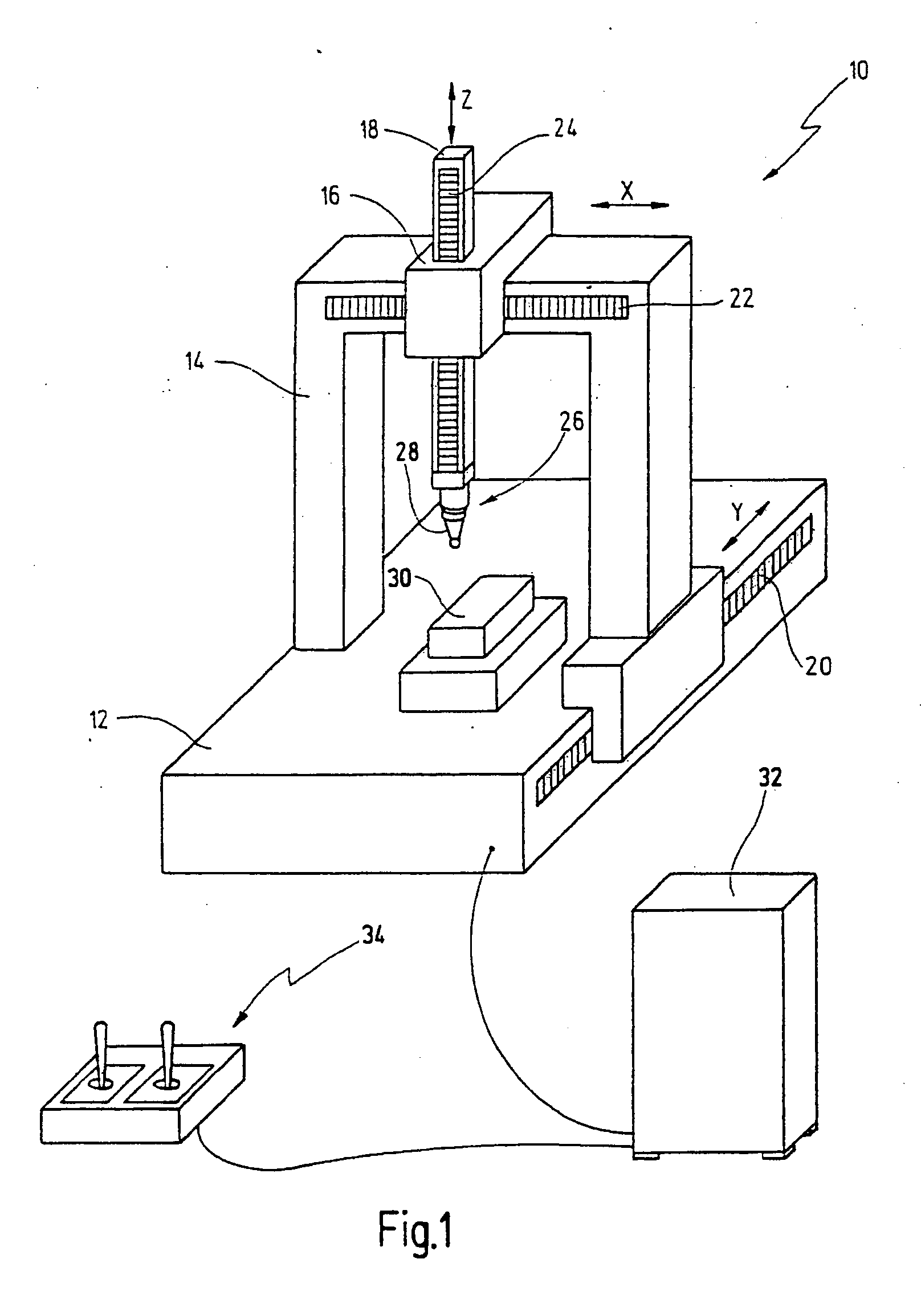
[0050] In FIG. 1, a coordinate measuring machine is denoted in its entirety by the reference number 10. The coordinate measuring machine 10 has a base plate 12 on which a portal 14 is arranged such that it can move in a longitudinal direction. The longitudinal direction is usually denoted as the y-axis. A slide 16 which can be moved in the x-direction is arranged on the upper crossbar of the portal 14 and, in turn, supports a ram 18 which can be adjusted in the z-direction. The reference numbers 20, 22, 24 denote scales from which the respective adjustment position of the portal 14, of the slide 16 and of the ram 18 in the three spatial directions x, y and z can be read off. In this case, the scales 20, 22, 24 may be typical measurement scales which can be read off from by an operator of the coordinate measuring machine 10. However, as an alternative and / or in addition, these may also be distance-measuring sensors which can be read out by machine.

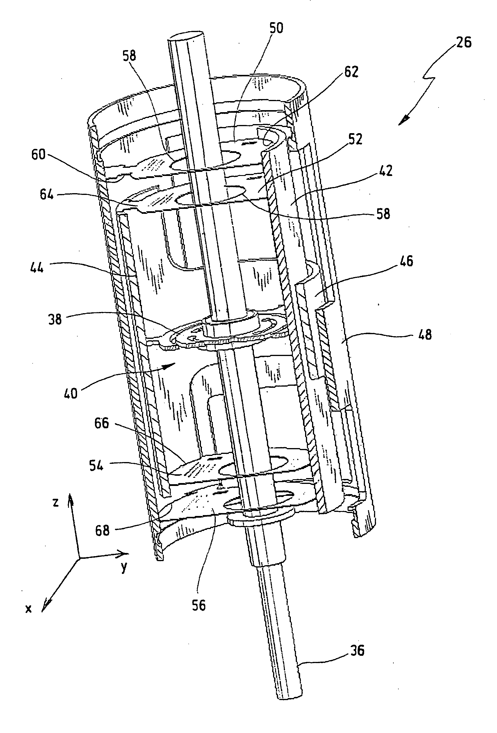
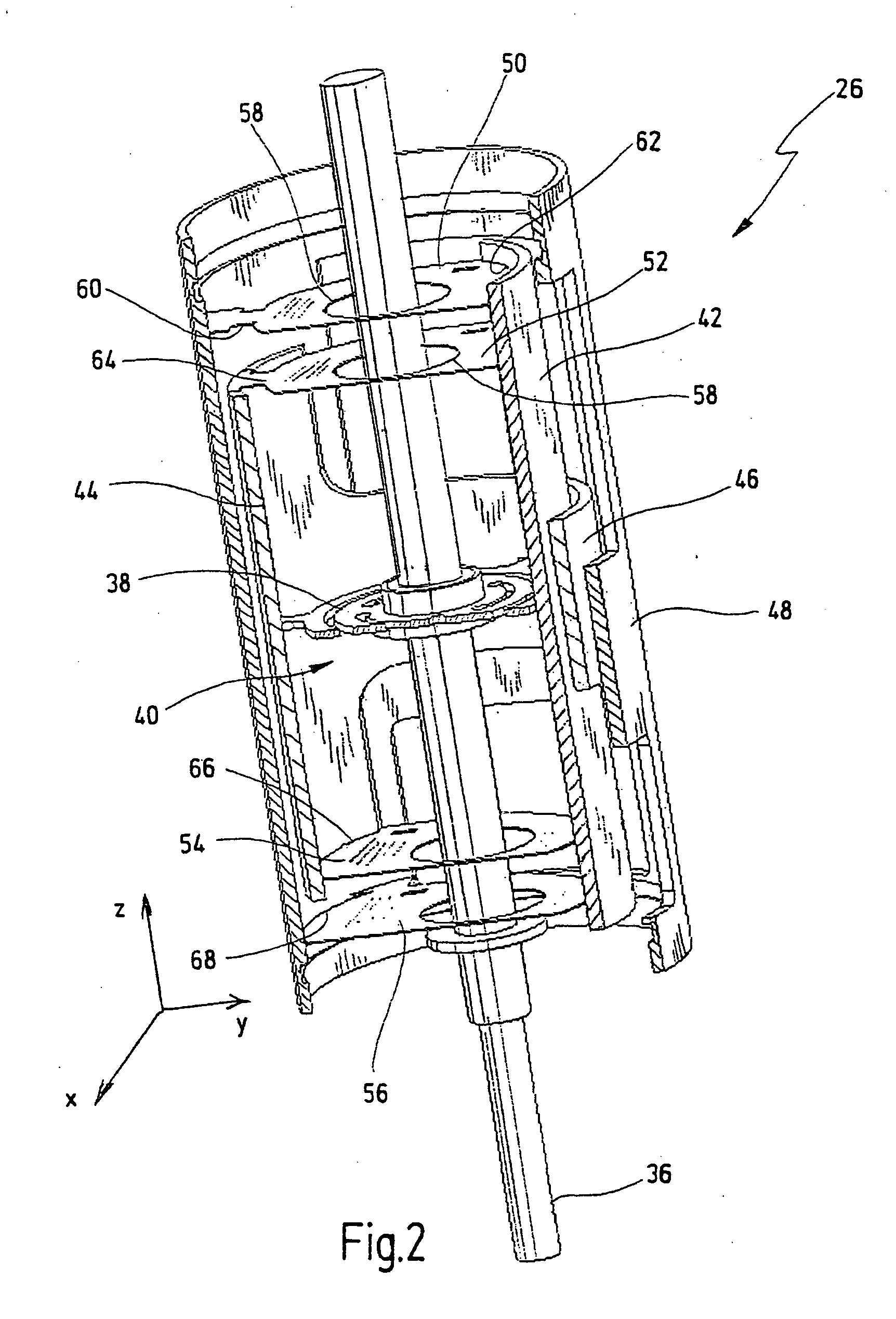
[0051] A probe 26, which has a feel...


PUM


Abstract

A probe for a coordinate measuring machine has a stationary first part and a second part which can move relative to said first part. The second part can be a feeler pin or a feeler pin extension of the probe. A damping member for damping vibrations of the moveable second part has a magnet arrangement for producing a magnetic field, and has a conductor element. The magnet arrangement is designed such that there is a change in direction of the magnetic field along a path of movement of the conductor element.

Description

CROSSREFERENCE TO RELATED APPLICATIONS [0001] This application is a continuation of international patent application PCT / EP2005 / 001867, filed on Feb. 23, 2005 and published in German language, which international application claims priority from German patent application DE 10 2004 011 730.6 filed on Mar. 5, 2004.BACKGROUND OF THE INVENTION [0002] The present invention relates to a coordinate measuring machine and more particularly to a probe for such a coordinate measuring machine. Even more particularly, the present invention relates to a damping mechanism for damping vibrations in such a probe. [0003] Coordinate measuring machines are used to measure the shape of an object to be measured with a high degree of accuracy. A typical application is the measurement of machine-produced workpieces in the course of quality control during production. The shape of the object is measured by moving the probe to defined points of the object by means of the moving frame, and then determining th...

Claims


Application Information

Patent Timeline
Patent Type & Authority Applications(United States)
IPC IPC(8): A61B5/05G01B5/00G01B7/012G01D11/14
CPCG01B7/012
Inventor ENDERLE, ECKHARDHERB, MONIKA
Owner CARL ZEISS IND MESSTECHN GMBH
Why Eureka
Try Eureka