
Explosion-proof dehumidification system

a dehumidification system and explosion-proof technology, applied in the direction of domestic cooling apparatus, heating types, separation processes, etc., can solve the problems of ineffective dehumidification system, mixed use of cooling-based dehumidification systems, and ineffective dehumidification system at removing moisture from the air, so as to discourage the build-up of electrostatic charges

Active Publication Date: 2007-03-15
AGGREKO +1
View PDF12 Cites 28 Cited by
  • Summary
  • Abstract
  • Description
  • Claims
  • Application Information

AI Technical Summary

Benefits of technology

[0009] According to another broad aspect of an embodiment of the present invention, there is provided a desiccant wheel assembly for use in a dehumidification system. The desiccant wheel assembly includes a cabinet and a desiccant wheel rotatively mounted within the cabinet. The desiccant wheel has a core impregnated with a desiccant material and an electrically conductive outer shell surrounding the core. Means are provided for driving rotation of the desiccant wheel within the cabinet. The desiccant wheel assembly further includes a static control device connected to a ground and associated with the desiccant wheel for discouraging the build-up of electrostatic charges on the desiccant wheel during rotation thereof.

Problems solved by technology

The use of such systems however has had mixed results.
While these systems have tended to be effective at removing moisture from the air in regions where the ambient temperature is generally warm and the humidity is relatively high, they have tended not to perform well in regions where the climate tends to be colder.
In particular, cooling-based dehumidification systems tend to become inefficient at removing moisture from the air when the dew point of the air approaches 0° C. because at that temperature the moisture freezes on the condensing coil.
Accordingly, cooling-based dehumidification systems have been found to be ill-suited for use in hazardous environments located in cold climates.
While such systems tend perform well in colder climates, conventional desiccant-type dehumidification systems have tended not to be employed in hazardous environments.
Both of these requirements tend to create significant explosion and ignition risks in a hazardous environment.
Moreover, the risk of explosion or ignition is further compounded by the fact that rotation of the wheel and the drying action of the desiccant tend to promote the generation of significant static electrical charges.
The build-up of these static electrical charges can result in electrostatic discharge causing sparking.
In a hazardous location, sparking can ignite flammable or combustible vapours in the ambient air.

Method used


Image

  • Explosion-proof dehumidification system
  • Explosion-proof dehumidification system
  • Explosion-proof dehumidification system

Examples


Embodiment Construction

[0024] The description which follows, and the embodiments described therein are provided by way of illustration of an example, or examples of particular embodiments of principles and aspects of the present invention. These examples are provided for the purposes of explanation and not of limitation, of those principles of the invention. In the description that follows, like parts are marked throughout the specification and the drawings with the same respective reference numerals.

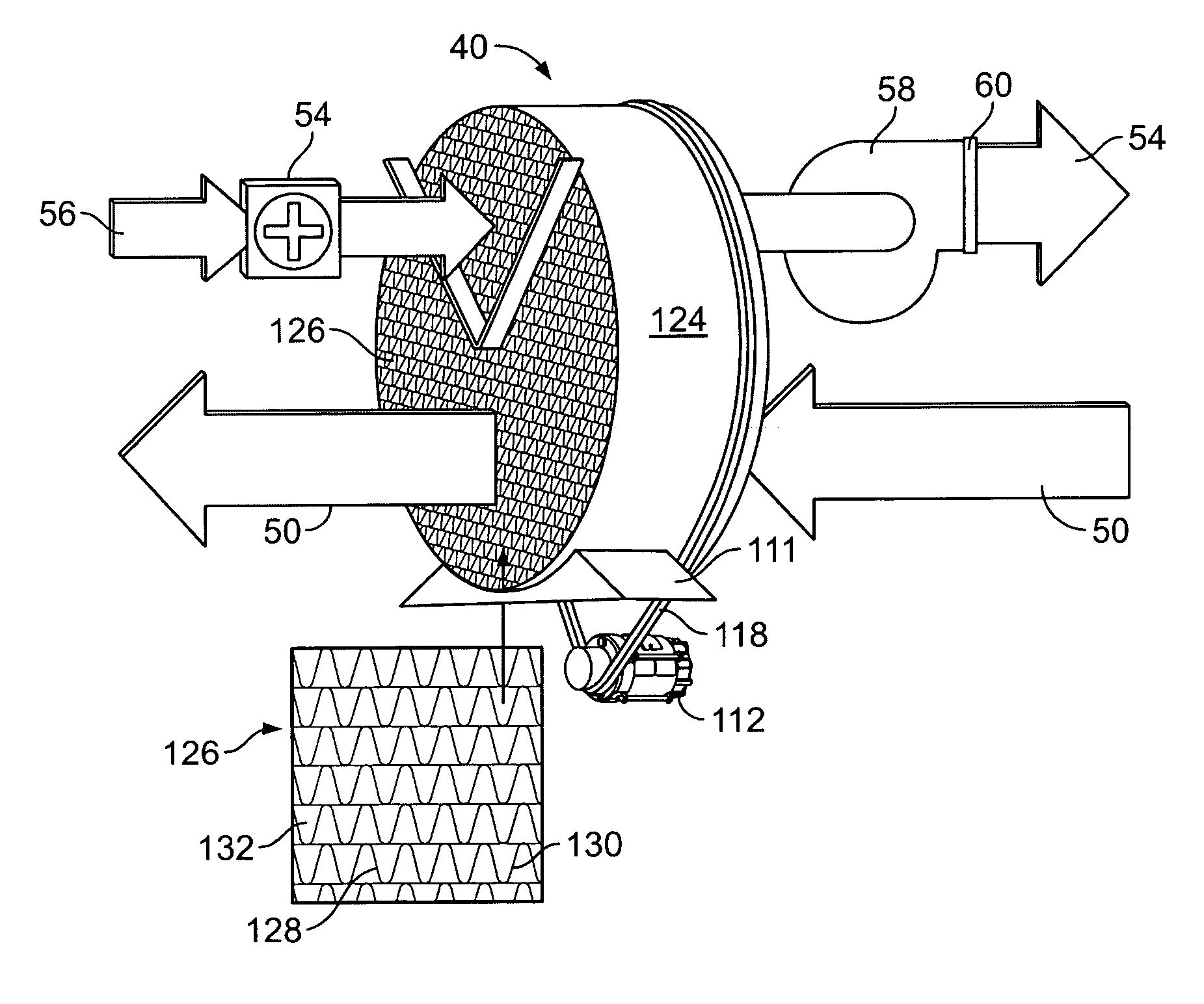
[0025] With regard to nomenclature, the term “explosion-proof” as it is used throughout the specification in connection with the dehumidification system described herein or any electrical component, element, part, module, or motor thereof, means that the enclosure thereof is capable of withstanding the pressure of an explosive mixture exploding inside the enclosure without rupture and capable of preventing the propagation of an explosion inside the enclosure to the atmosphere surrounding the enclosure.

[0026...


PUM

PropertyMeasurementUnit
diameteraaaaaaaaaa
temperatureaaaaaaaaaa

Abstract

The present invention relates to dehumidification equipment and more particularly, to a dehumidification system and method for use in hazardous locations. In particular, there is provided a desiccant wheel assembly for use in a dehumidification system. The desiccant wheel assembly includes a cabinet and a desiccant wheel rotatively mounted within the cabinet. The desiccant wheel has a core impregnated with a desiccant material and an electrically conductive outer shell surrounding the core. Means are provided for driving rotation of the desiccant wheel within the cabinet. The desiccant wheel assembly further includes a static control device connected to a ground and associated with the desiccant wheel for discouraging the build-up of electrostatic charges on the desiccant wheel during rotation thereof. A dehumidification system comprising such a desiccant wheel assembly is also described along with a method for dehumidifying air in an enclosed space using a desiccant wheel dehumidification system.

Description

FIELD OF THE INVENTION [0001] The present invention relates to dehumidification equipment and more particularly, to a dehumidification method and apparatus for use in hazardous locations. BACKGROUND OF THE INVENTION [0002] Humidity control is a primary concern in many industries. Accordingly, over the years, various techniques have been developed to address these concerns. One such technique to control humidity combines cooling and condensation principles to remove humidity from air. The air in an enclosed space is cooled until it reaches a temperature below its dew point temperature at which time the moisture in the air condenses on the nearest surface. Conventional cooling-based dehumidification systems typically include a cooling coil, a condensing coil and a compressor. [0003] While these types of systems are capable of extracting moisture from the air, it should be noted that they are primarily designed for cooling air. Nonetheless, the use of cooling-based dehumidification sys...

Claims


Application Information

Patent Timeline
Patent Type & Authority Applications(United States)
IPC IPC(8): F23L15/02F25D17/06F25D23/00
CPCB01D53/06B01D53/261B01D2251/302B01D2251/60B01D2253/106B01D2253/108F24F2203/1032B01D2253/304B01D2253/342B01D2257/80B01D2259/4009F24F3/1423B01D2253/25
Inventor CAGGIANO, MARIO
Owner AGGREKO
Features
  • Generate Ideas
  • Intellectual Property
  • Life Sciences
  • Materials
  • Tech Scout
  • Unparalleled Data Quality
  • Higher Quality Content
  • 60% Fewer Hallucinations
Learn More