Brake system for a well service or drilling hoist

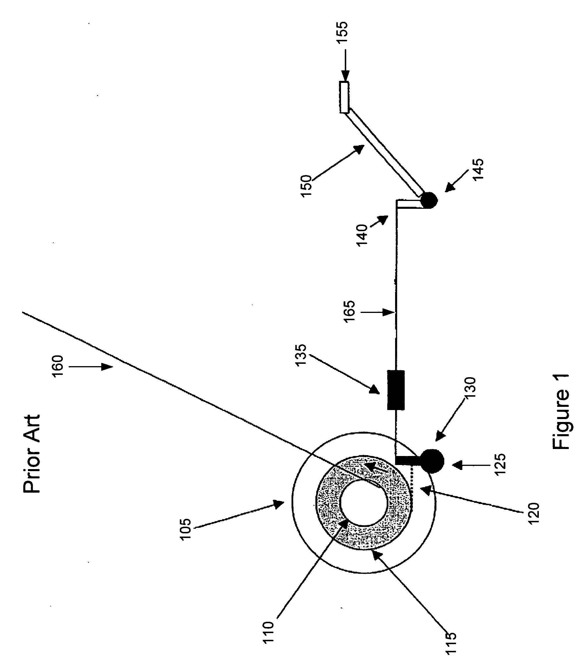
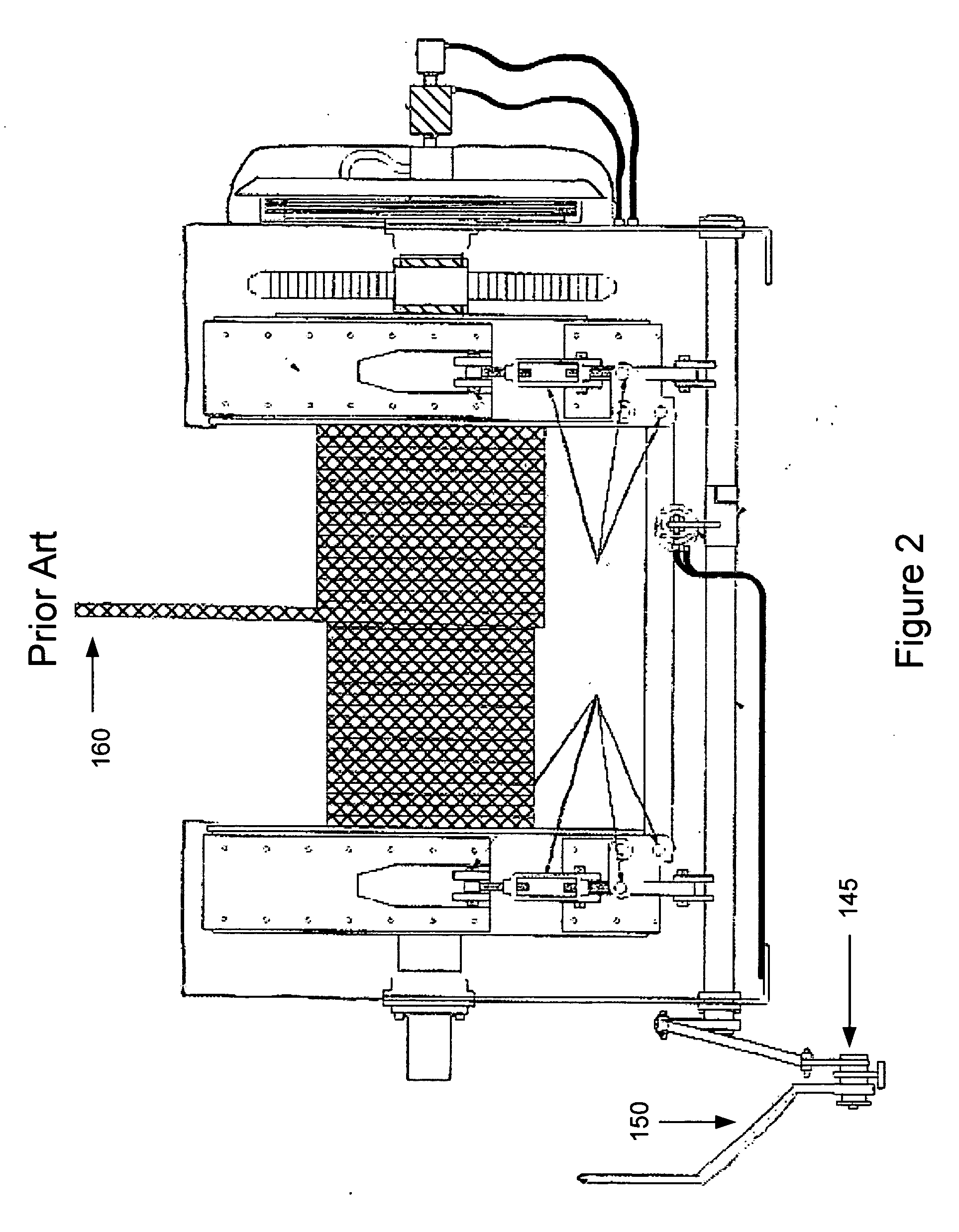
a technology for hoists and brake systems, which is applied in the direction of mechanically actuated drum brakes, hoisting equipment, emulsification, etc., can solve the problems of operator inadvertently exceeding the safe position of the traveling block, equipment damage, and hazard to personnel working on the equipmen

Active Publication Date: 2007-03-15
KEY ENERGY SERVICES
View PDF9 Cites 10 Cited by
  • Summary
  • Abstract
  • Description
  • Claims
  • Application Information

AI Technical Summary

Benefits of technology

[0011] The present invention supports a braking system that allows the actuating cylinder to be mechanically independent and unlinked from the brake handle so that when the brakes are set due to the detection of a crown out, floor out, or other action or problem the brake handle will not be jerked out of the operator's hand and potentially cause injury.
[0013] For another aspect of the present invention, the brake system can include brake flanges positioned on each side of a tubing drum. One or more brake bands can be frictionally engagable with each of the brake flanges. An equalizer bar can be coupled to the brake bands. The equalizer bar is capable of rotating about a fixed point to increase or decrease the tension on the brake bands. A linkage system can be coupled to the equalizer bar for transferring energy from a bell crank that can rotate about another fixed point. A brake lever can include an arm coupled thereto. The brake lever can rotate about a fixed point that is the same as or different than the bell crank. Upon receiving a force, the brake lever can rotate in a direction about the fixed point and the arm can strike the bell crank and cause it to rotate in the same direction during the period of contact between the arm and the bell crank. The brake system can further include a spring coupled between the brake lever and the bell crank. When the brake lever is lifted to reduce the tension of the brake bands on the brake flange, the spring can transmit the lifting force of the brake lever to the bell crank, thereby causing the bell crank to rotate in the same direction as the brake lever and further transmitting the rotational energy to the equalizer bar to reduce braking on the tubing drum.

Problems solved by technology

Crown out / floor out can result in equipment damage and present a hazard to personnel working on the equipment.
Because it is often not possible for the operator of the cable hoist system to see the position of the traveling block, or because the operator can be otherwise distracted from monitoring the position of the traveling block, the operator can inadvertently exceed safe positions of the traveling block.
As the rig trips into the hole with heavy loads, the braking system heats up and the brake bands 120 expand, which can cause slack in the system 100.
Therefore, there is a need in the art for a braking system that allows the actuating cylinder to act independently of the brake handle so that when the brakes are set due to the detection of a crown out, floor out or other action or problem the brake handle will not be jerked out of the operator's hand and potentially cause injury.

Method used


Image

  • Brake system for a well service or drilling hoist
  • Brake system for a well service or drilling hoist
  • Brake system for a well service or drilling hoist

Examples


Embodiment Construction

[0024] Exemplary embodiments of the present invention will now be described in detail with reference to the figures for an exemplary operating environment of operating a drum braking assembly for a well service or drilling hoist. While the exemplary braking system of the present invention is described in the context of an operative environment used for braking systems to slow or stop a drum on a well service or drilling hoist, those of ordinary skill in the art will recognize that the braking system can be used in many other applications to slow or stop other types of vehicles or devices.

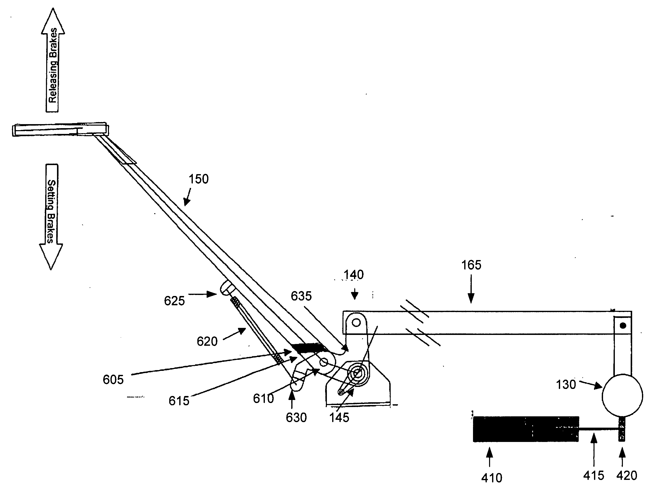
[0025] A method and system for a brake lever pivoting about a bell crank to activate a braking system will now be described more fully hereinafter with reference to FIGS. 6-8, which show an exemplary embodiment of the present invention. Turning now to FIG. 6, the exemplary drum braking system 600 includes a brake handle 155 attached to a brake lever 150. The brake lever 150 extends between the brak...


PUM

PropertyMeasurementUnit
forceaaaaaaaaaa
rotational movementaaaaaaaaaa
distanceaaaaaaaaaa

Abstract

The brake system includes a brake lever independent of, but capable of rotating about the same point as a bell crank. Upon receiving a downward force, a member extending from the lever strikes a portion of the bell crank and generates a force that cause the bell crank to rotate. Rotational action of the bell crank transfers rotational energy to an equalizer bar thorough a linkage system. The equalizer bar's rotation increases or decreases tension on brake bands that slow a tubing drum. A cylinder can activate and cause the equalizer bar to rotate, applying tension to the brake bands and slowing the drum. Rotational energy is transferred back to the bell crank through the linkage. The rotational energy is absorbed by a spring positioned between the bell crank and the brake lever, thereby reducing the amount of sudden force passed through the brake lever to an operator.

Description

STATEMENT OF RELATED PATENT APPLICATION [0001] This non-provisional patent application claims priority under 35 U.S.C. § 119 to U.S. Provisional Patent Application No. 60 / 716,673, titled A Brake Handle Pivotal Around a Bell Crank For a Well Service or Drilling Hoist, filed Sep. 13, 2005. This provisional application is hereby fully incorporated herein by reference.FIELD OF THE INVENTION [0002] The present invention relates to braking systems. More specifically, the present invention relates to a brake system for hoist drums such as those used on drilling rigs, well service rigs, and the like. BACKGROUND OF THE INVENTION [0003] After an oil drilling rig drills a well and installs the well casing, the rig is dismantled and removed from the site. From that point on, a mobile repair unit, or workover rig, is typically used to service the well. Servicing includes, for example, installing and removing inner tubing strings, sucker rods, and pumps. This is generally done with a cable hoist ...

Claims


Application Information

Patent Timeline
Patent Type & Authority Applications(United States)
IPC IPC(8): F16D55/16B01F23/47
CPCB60T7/10B66D5/10F16D51/04F16D49/20B66D5/24
Inventor NEWMAN, FREDERIC M.
Owner KEY ENERGY SERVICES
Why Eureka
Try Eureka