Brake assembly with rust jacking

a technology of brake components and rust, which is applied in the direction of braking members, coatings, friction linings, etc., can solve the problems of friction lining cracking, less efficient braking, corrosion or rust at the interface of the brake table, etc., and achieve the effect of preventing corrosion

Inactive Publication Date: 2007-03-15
ARVINMERITOR TECH
View PDF25 Cites 22 Cited by
  • Summary
  • Abstract
  • Description
  • Claims
  • Application Information

AI Technical Summary

Benefits of technology

[0006] A brake pad or shoe assembly includes a sealing bearing that prevents corrosion between a friction lining and a support plate. A liquid material is initially applied to at least one of the support plate and friction lining. After application of the liquid material, the friction lining is fastened to the brake table with a plurality of fasteners. The liquid material subsequently forms the sealing barrier.
[0010] The sealing barrier is solely relied upon to provide a sealed interface between the friction lining and the support plate. Fasteners are relied upon to secure the friction lining to the support plate. This configuration allows worn friction linings to be easily and efficiently replaced. The worn friction lining is removed from the support plate, liquid material is applied as discussed above, and a new friction lining is secured to the support plate.
[0011] In addition to allowing worn friction linings to be easily replaced, the subject sealing barrier prevents rust / corrosion from forming between the friction lining and support plate, which results in improved brake performance and longer friction lining life.

Problems solved by technology

Corrosion or rust can develop at an interface between the brake table and friction lining.
Over time this rust or corrosion can expand or grow, which can cause a separation of the friction lining from an outer surface of the brake table.
This can deform the friction lining from its intended shape resulting in less efficient braking.
Further, this expansion force, in combination with an attachment force of the adhesive or fastener, acting in an opposing direction from the expansion force, can cause the friction lining to crack.
This can accelerate wear of the friction lining.
Further, governmental restrictions can require a vehicle with cracked linings to be taken out of service.
However, once a friction lining has worn, it is difficult and time consuming to replace the worn lining with a new friction lining due to the double-sided adhesive liner.

Method used


Image

  • Brake assembly with rust jacking
  • Brake assembly with rust jacking
  • Brake assembly with rust jacking

Examples


Embodiment Construction

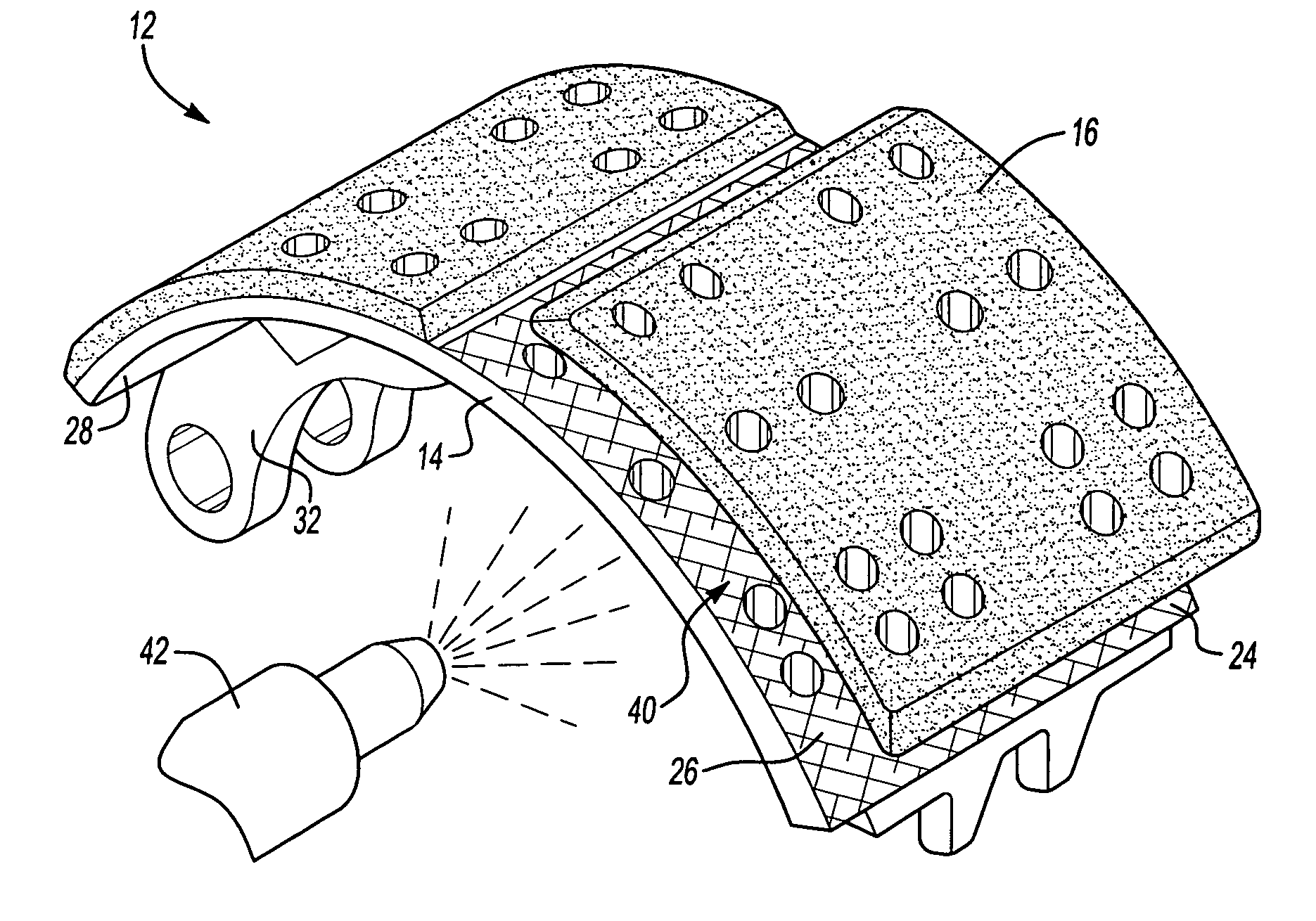
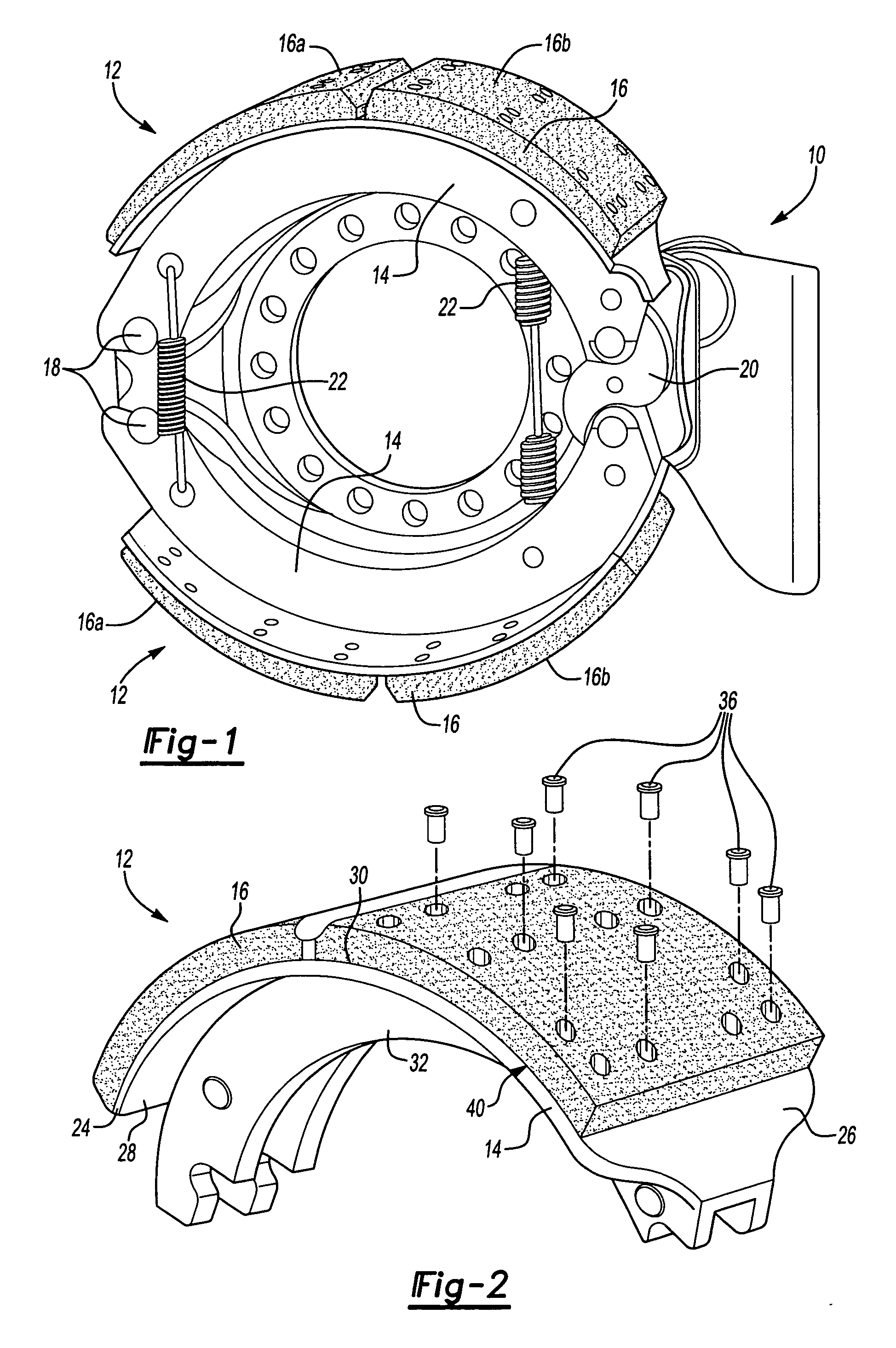
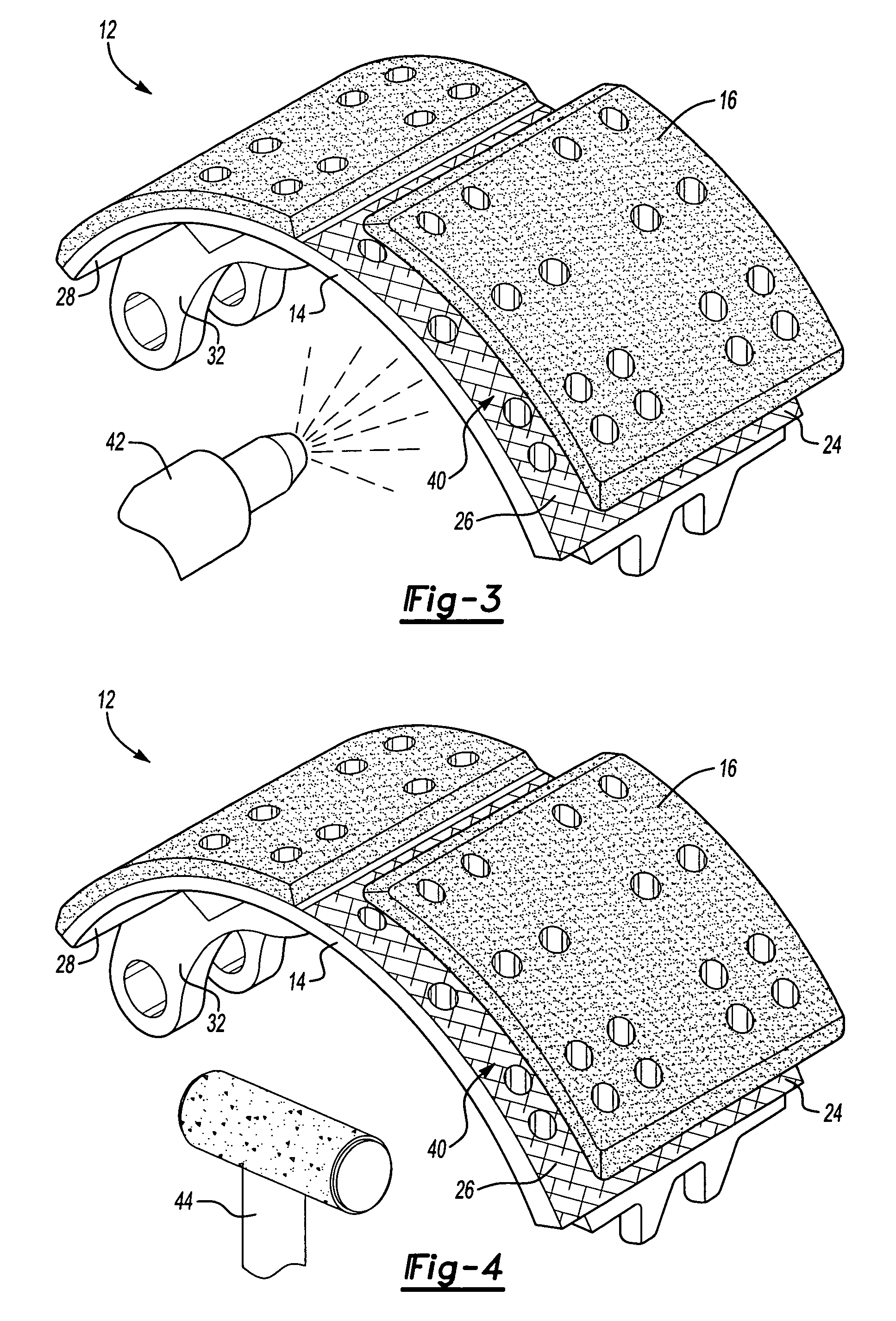
[0020] A brake assembly 10 is shown in FIG. 1. The brake assembly includes brake pads or brake shoes 12, with each brake shoe 12 having a support plate or brake table 14 and a friction lining 16. The friction lining 16 is formed as a lining block that is fixed to the brake table 14. In the example shown, first 16a and second 16b lining blocks are fixed to the brake table 14, however, a single lining block or additional lining blocks could also be used.

[0021] Each brake shoe 12 is fixed at one end with an anchor pin 18. An actuator 20 is associated with an opposite end of each brake shoe 12 and is used to move the brake shoes 12 into engagement with a rotating brake component such as a brake drum (not shown), for example. In the example shown, the actuator 20 comprises an S-cam that moves the brake shoes 12 in response to a brake command. Other types of actuators 20 could also be used such as wedges or hydraulic cylinders, for example. Resilient members 22 assist in returning the br...


PUM

PropertyMeasurementUnit
frictionaaaaaaaaaa
web structureaaaaaaaaaa
liquidaaaaaaaaaa

Abstract

A brake component assembly includes a support plate and a friction lining mounted to the support plate with a plurality of fasteners. A sealing barrier is formed between the support plate and the friction lining. A liquid material is initially applied to at least one of the support plate and friction lining, which are then fastened together. The liquid material subsequently forms the sealing barrier between the support plate and the friction lining. Optionally, a flexible gasket is used to form the sealing barrier. The flexible gasket is sandwiched between the support plate and friction lining when the support plate and friction lining are fastened together.

Description

TECHNICAL FIELD [0001] The subject invention relates to a brake component assembly with a friction lining supported on a plate with a sealing barrier formed between the friction lining and plate. BACKGROUND OF THE INVENTION [0002] Brake shoe and pad assemblies utilize a friction lining that is supported on a plate, which is often referred to as a brake table. Traditionally, an adhesive or a plurality of fasteners is used to attach the friction lining to the brake table. In response to a braking command, an actuator moves the brake shoe or pad assembly such that the friction lining contacts a rotating brake component, such as a drum or disc. [0003] Corrosion or rust can develop at an interface between the brake table and friction lining. Over time this rust or corrosion can expand or grow, which can cause a separation of the friction lining from an outer surface of the brake table. This can deform the friction lining from its intended shape resulting in less efficient braking. Furthe...

Claims


Application Information

Patent Timeline
Patent Type & Authority Applications(United States)
IPC IPC(8): F16D65/04
CPCF16D65/04F16D69/04F16D2250/0046F16D2069/0433F16D2069/005
Inventor HAYFORD, ROY LEEKAY, JOSEPH A.GIANGRANDE, HOLLY ANN
Owner ARVINMERITOR TECH
Why Eureka
Try Eureka