Method and an arrangement for transport layer control signalling in utran supporting both atm and ip transport technologies

Inactive Publication Date: 2007-03-15
TELEFON AB LM ERICSSON (PUBL)
View PDF3 Cites 9 Cited by
  • Summary
  • Abstract
  • Description
  • Claims
  • Application Information

AI Technical Summary

Benefits of technology

[0030] Another advantage with the solution according to the present invention is that it is possible to perform dynamic configuration of the ATM layer while in the prior art solution with Q.AAL2 and

Problems solved by technology

Q.2630 is used to establish AAL2 connections in ATM UTRAN network but Q.2630 signalling is not suitable to configure ATM layer.
It is not suitable to use IP-ALCAP for making resource reservations in IP routers and Diffserv based resource reservation scheme like RMD cannot be used.
In addition, it is not possible to use IP-ALCAP so

Method used


Image

  • Method and an arrangement for transport layer control signalling in utran supporting both atm and ip transport technologies
  • Method and an arrangement for transport layer control signalling in utran supporting both atm and ip transport technologies
  • Method and an arrangement for transport layer control signalling in utran supporting both atm and ip transport technologies

Examples


first embodiment

[0049] In accordance with the present invention, the TNL signalling solution is adapted for implementation in an IP based UTRAN. One RSVP-TE tunnel is established for each connection and standard RSVP-TE objects and messages are used as mentioned above. In order to achieve bi-directional reservation, one tunnel is established for downstream and another tunnel for upstream user traffic.

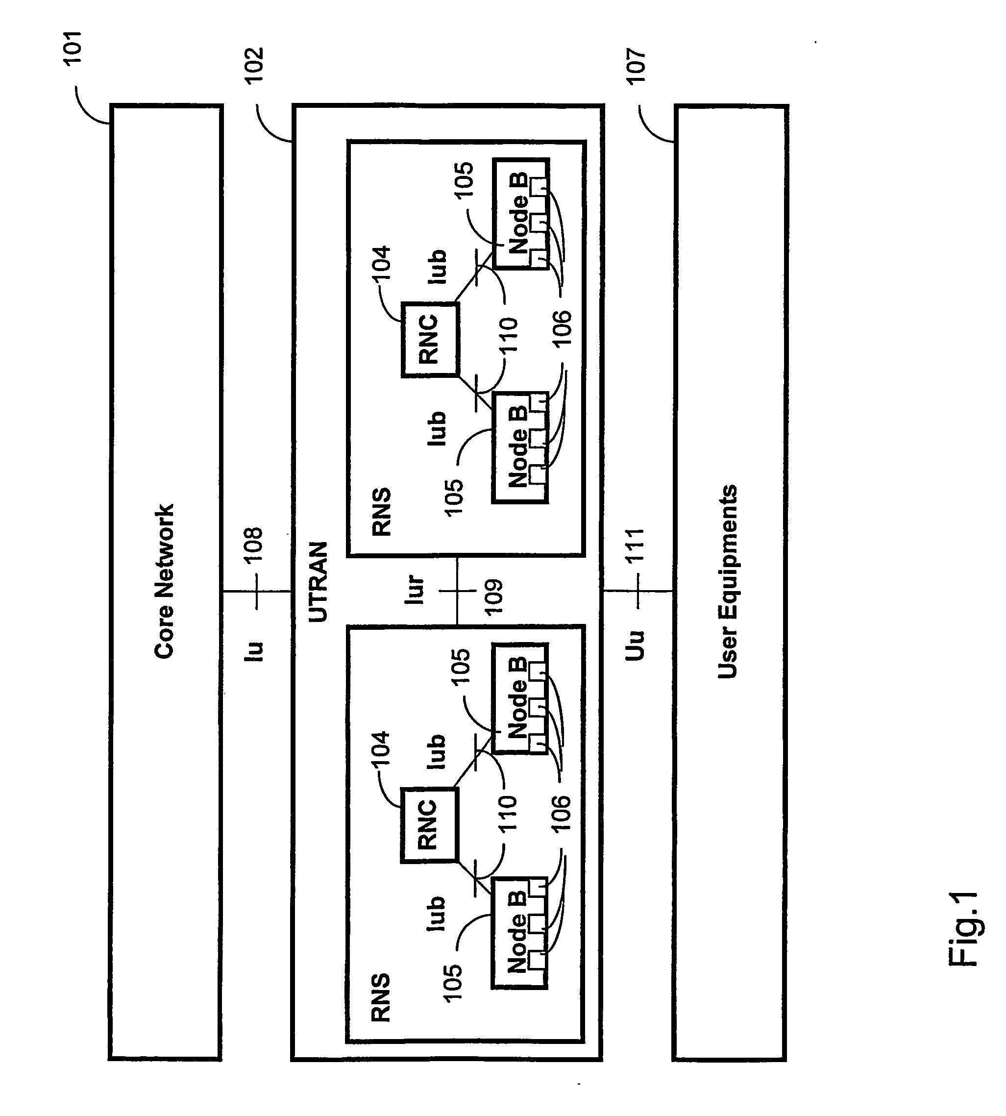
[0050] The network model between the RNC and the Node B in case of a full IP based network according to the first embodiment of the present invention is shown in FIG. 3a. It comprises an RNC, a Node B (also denoted base station) and interior routers. The RNC and the Node B are edge nodes using the terminology of the RMD concept.

[0051] The solution according to first embodiment of the invention may also be used in the case of mixed IP / ATM network, in which an Inter-working Unit (IWU) is adapted to operate between the IP and the ATM network parts. This scenario is shown in FIG. 3b. In this case the IWU ...

second embodiment

[0064] The TNL signalling is in the following way:

[0065] The TNL signalling is adapted to control both ATM and AAL2 layers of AAL2 switches. So, the establishment of a new AAL2 connection may initiate the creation or modification of ATM VCs.

[0066] Moreover, the TNL signalling may also be adapted to control the AAL2 layer only. The ATM layer of AAL2 switches is configured semi-permanently by standard RSVP-TE or via the management system. This is denoted as RSVP-TE(ATM) and is performed according to prior art.

[0067] The model of the UTRAN between an RNC and a Node B and a basic unidirectional signalling operation are shown in FIG. 4a in the network part between the RNC and ALL2 switch, indicated in FIG. 4a, the ATM network layer is semi-permanent while the other part (between AAL2 switch and Node B) it is set up dynamically on-demand. (Could you explain this further. I don't understand the figure with the arrows.) This means that between RNC and AAL2 switch only the AAL2 layer is c...

third embodiment

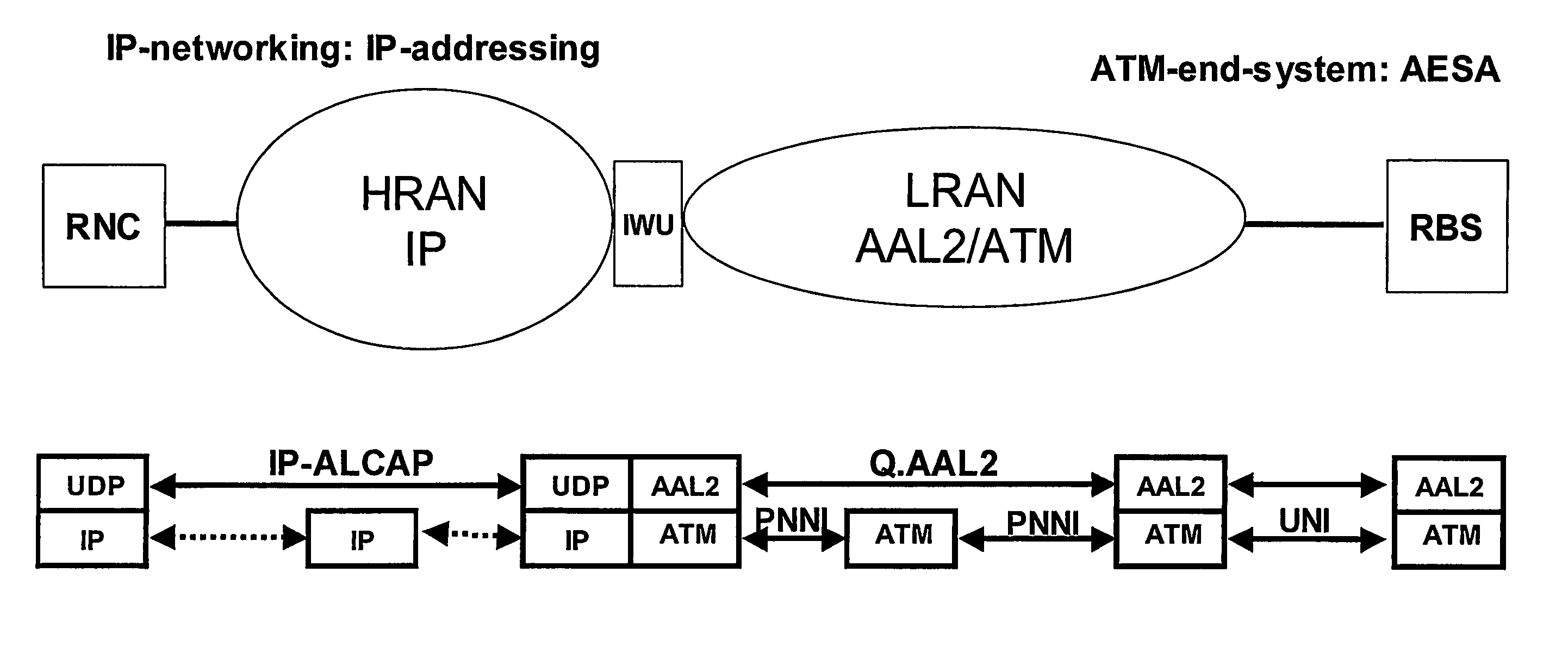
[0085] According to the present invention, the proposed TNL signalling may also be used in a mixed ATM-IP network, in which HRAN is IP based and LRAN is ATM based. An Inter-working Unit (IWU) operates between the ATM and IP network parts, see FIG. 2b. In the user plane, the IWU converts the IP packets to ATM packets, but the IWU is not needed for the control plane, which is an advantage of the present invention.

[0086] The method according to the present invention is illustrated by the flowchart in FIG. 7. Thus, the method for controlling the user plane of a UMTS Terrestrial Radio Access Network, UTRAN, comprising a first edge node connected via a Transport Network Layer to a second edge node, by using Transport Network Layer, TNL, signalling, comprises the steps of: [0087] 701. Transmitting RSVP-TE based TNL signalling messages between said first and second edge nodes for each TNL flow, [0088] 702. Identifying each TNL flow by using RSVP-TE messages, wherein the object SESSION and S...


PUM


Abstract

The present invention relates to a method and an arrangement for controlling the user plane of a UMTS Terrestrial Radio Access Network, UTRAN, comprising a first edge node connected via a Transport Network Layer to a second edge node, by using Transport Network Layer, TNL, signalling. A radio link is set up by using the Node B Application Part between the first and second edge nodes of the UTRAN, RSVP-TE based TNL signalling messages are transmitted between said first and second edge nodes for each TNL flow, and each TNL flow is identified by using RSVP-TE messages, wherein the object SESSION and SENDER_TEMPLATE comprises an IP based 5-tuple flow information, which is adapted to be used as a TNL flow identity.

Description

FIELD OF THE INVENTION [0001] The present invention relates to a method and an arrangement in a mobile telephone network. In particular, it relates a method and an arrangement for transport network layer (TNL) control signaling in a Universal Mobile Telephony System Terrestrial Radio Access Network (UTRAN). BACKGROUND [0002] UMTS Terrestrial Radio Access Network (UTRAN) is the Radio Access Network (RAN) of 3rd generation mobile networks specified by 3GPP standardisation organization. The general protocol model of UTRAN Interfaces is shown in FIG. 2a. The protocol model can be split up into two logically independent layers: a Radio Network Layer (RNL) and a Transport Network Layer (TNL), and orthogonally into User and Control planes as further described in 3GPP TS 25.401, 3GPP, TSG RAN: UTRAN overall description. [0003] According to FIG. 1, the main parts of the UTMS are a core network 101, the UTRAN 102, and user equipments (UE) 107 also referred to as mobile terminals. The interfac...

Claims


Application Information

Patent Timeline
IPC IPC(8): H04J3/14H04L12/56H04L12/54H04W28/26H04W76/02
CPCH04L12/5601H04L12/5695H04L47/724H04L47/824H04L47/825H04L69/08H04L2012/563H04L2012/5667H04W28/26H04W76/02H04L2012/5607H04L47/70H04W76/10
Inventor ANTAL, CSABAMUSIKKA, NIILOBADER, ATTILAWESTBERG, LARS
Owner TELEFON AB LM ERICSSON (PUBL)
Why Eureka
Try Eureka