
Load computer programmed to simulate a thermal load of an x-ray device

a technology of x-ray device and load computer, which is applied in the field of load computer with a program for implementing a method for simulation of a thermal load of an x-ray device and a load computer, can solve the problems of inability to simply transfer methods to different x-ray tubes and anodes, high computational costs, and inability to calculate the temperature distribution. , to achieve the effect of high utilization of x-ray devices, high computational efficiency and high simulation efficiency

Inactive Publication Date: 2007-03-15
SIEMENS AG
View PDF8 Cites 2 Cited by
  • Summary
  • Abstract
  • Description
  • Claims
  • Application Information

AI Technical Summary

Benefits of technology

"The invention provides a load computer and method for simulating the thermal load of an x-ray detector. The load computer has a program that predicts the temperature of the detector using a solution function that takes into account the cooling fluid and the power radiated onto the detector. The load computer can be used to quickly and accurately simulate the thermal load of the detector, leading to higher utilization of the x-ray device. The invention also provides a method for simulating the thermal load of other heat sources, such as electrical consumers, using the same load computer. Overall, the invention provides a way to achieve a high level of safety and disruption-free operation with a high utilization of the x-ray device."

Problems solved by technology

One disadvantage of this method is that the method for calculation of the temperature distribution requires a high computational outlay.
In particular, operation of the load computer in real time is not possible.
The method can also not be simply transferred to different x-ray tubes and anode types.
The method implemented with the load computer is time-consuming and costly.
A disadvantage of the method is that no temperature of the x-ray device (such as, for example, the anode temperature) is taken into account.
This can lead to unnecessary interruptions and wait times. The capability (efficiency) of the x-ray tube cannot be fully utilized.

Method used


Image

  • Load computer programmed to simulate a thermal load of an x-ray device
  • Load computer programmed to simulate a thermal load of an x-ray device
  • Load computer programmed to simulate a thermal load of an x-ray device

Examples


Embodiment Construction

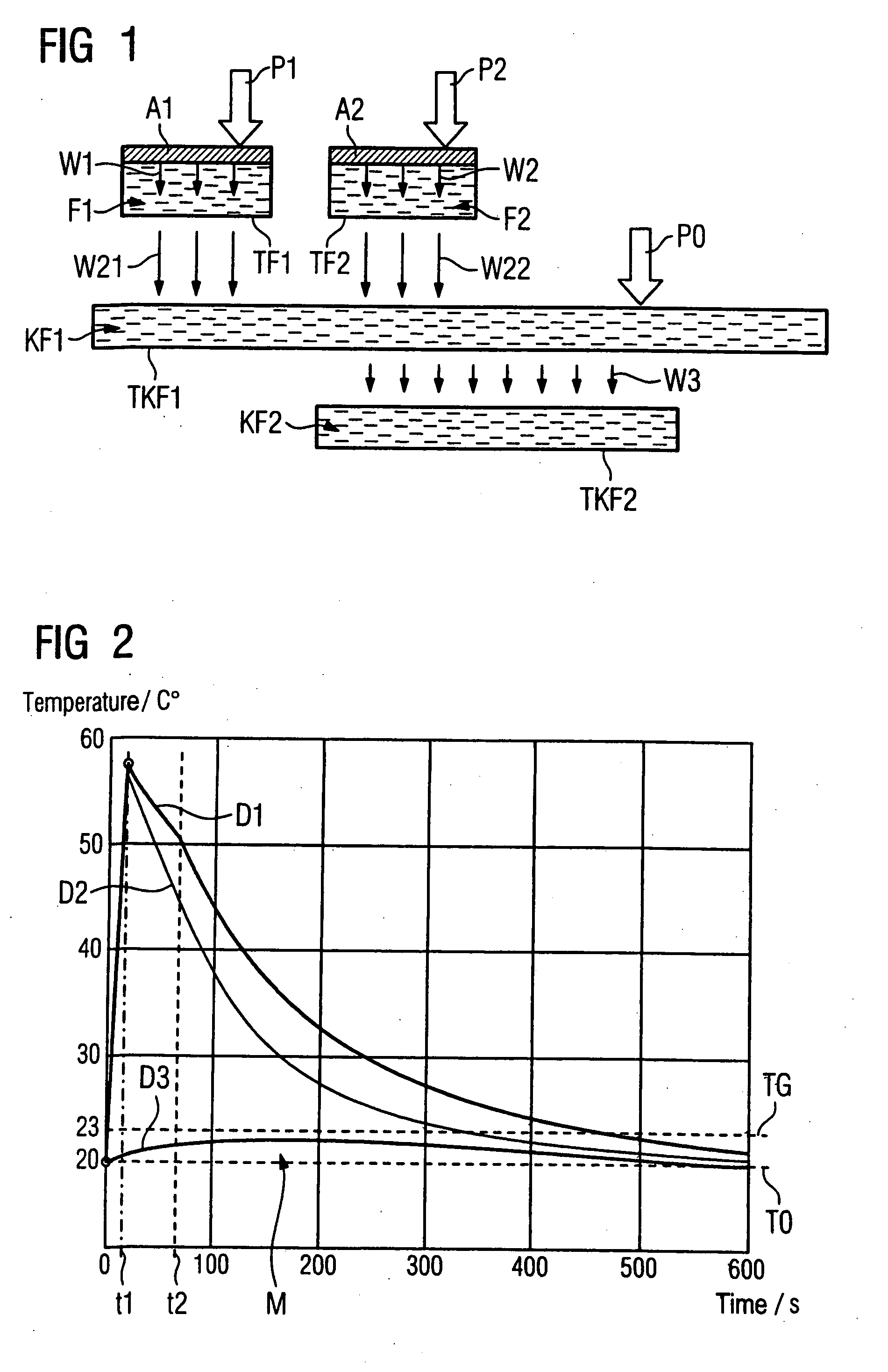
[0054]FIG. 1 shows a schematic model of a the flow in the x-ray device that forms the basis of the inventive method. A first anode A1 is loaded with a first power P1. A second anode A2 is loaded with a second power P2. A first fluid F1 is provided to cool the first anode A1 and a second fluid F2 is provided to cool the second anode A2. A first cooling fluid KF1 is provided to cool the first fluid F1 and second fluid F2. A loss power generated by a consumer is designated with P0. To cool the consumer this is thermally coupled with the first cooling fluid KF1. A second cooling fluid KF2 is provided to cool the first cooling fluid KF1. A first heat flow (caused by the first power (P1) from the first anode A1 to the first fluid F1 is designated with reference character W1. A second heat flow (caused by the second power P2) from the second anode A2 to the second fluid F2 is designated with the reference character W2. Third and fourth heat flows from the first fluid F1 and second fluid F2...


PUM


Abstract

A load computer with a program simulates the thermal load of an x-ray device having anodes, wherein an i-th fluid is provided for cooling the i-th anode and a first cooling fluid is provided for cooling the i-th fluids. The program simulates a first cooling temperature of the first cooling fluid, such that the thermal load is accurately simulated.

Description

BACKGROUND OF THE INVENTION [0001] 1. Field of the Invention [0002] The present invention concerns a load computer with a program for implementation of a method for simulation of a thermal load of an x-ray device and x-ray device. [0003] 2. Description of the Prior Art [0004] In x-ray devices, in particular tomography apparatuses, a load computer is typically used to monitor the thermal load of the x-ray tube. Such a load computer is known, for example, from DE 198 11 041. A spatiotemporal temperature distribution of the anode struck by electrons can be calculated with a method implemented by the known load computer. One disadvantage of this method is that the method for calculation of the temperature distribution requires a high computational outlay. In particular, operation of the load computer in real time is not possible. The method can also not be simply transferred to different x-ray tubes and anode types. The method must be adapted to properties of the x-ray tube and to the p...

Claims


Application Information

Patent Timeline
Patent Type & Authority Applications(United States)
IPC IPC(8): H05G1/28H05G1/00F25D23/12
CPCG01K7/42H01J2235/1262H01J2235/1204
Inventor EBERSBERGER, JOHANNES
Owner SIEMENS AG
Learn More