
Synchronization control system

a control system and synchronization technology, applied in the field of synchronization control systems, can solve the problems of not being suitable for long-term use, broad-based and inaccurate timing purposes, and severely limited methodological application for controlling heart assist devices, and achieve the effect of rapid correction of the condition

Inactive Publication Date: 2007-03-15
SUNSHINE HEART PTY LTD
View PDF16 Cites 24 Cited by
  • Summary
  • Abstract
  • Description
  • Claims
  • Application Information

AI Technical Summary

Benefits of technology

[0043] This rapid isolation of the cause of malfunction can assist in rapidly correcting the condition causing the malfunction. In the case of a patient dying it will prevent the heart assist device continuing to operate after death.

Problems solved by technology

This methodology is severely limited in its application for control of heart assist devices and the like for a number of reasons: 1.
Further, whilst the T-wave indicates ventricular repolarisation, it is broad-based and not very accurate for timing purposes; 2.
The systemic arterial blood pressure is very good at highlighting the time of aortic valve closure, but is only useful in a temporary manner, via a percutaneous arterial line, and is not suitable for long-term use; 3.
As the heart rate varies (particularly if the patient is suddenly exercising, or anxious, or the rhythm is in atrial fibrillation, or depending on the contractile state of the myocardium etc), time of opening and closure of the aortic valve after the R-wave of the ECG may vary significantly, thus whilst the beginning of systole can be relatively safely timed (and balloon deflation initiated), the timing of the beginning of diastole is not possible with ECG alone.
There is no reliable and accurate way to determine particularly the timing of aortic valve closure long-term in manner that allows patients to enjoy a good life-style whilst fitted with the device.
However, this requires the device functionality to be paused every 2-3 minutes to male measurements.
This does not allow precise control of device function to specific heart beats, rather, timings are set for 2 minutes, until the measurement is re-done.
Further, the dichrotic notch may not always be detected.
Another problem associated with components used to control partially implantable heart assist devices (i.e. having external drivers / controllers) is that the size, number, and rigidity of any percutaneous tubing or wires must be kept to a minimum to reduce the chance of infection and increase psychological acceptance of the devices.
However, the wireless telemetry associated with pacemakers is usually proprietary and unnecessarily complex, and is not suited for continuous discreet signal outputs.

Method used


Image

  • Synchronization control system
  • Synchronization control system
  • Synchronization control system

Examples


Embodiment Construction

[0052] By way of further background, the DSPT has the basic modalities of sensing, transmitting, and programmability.

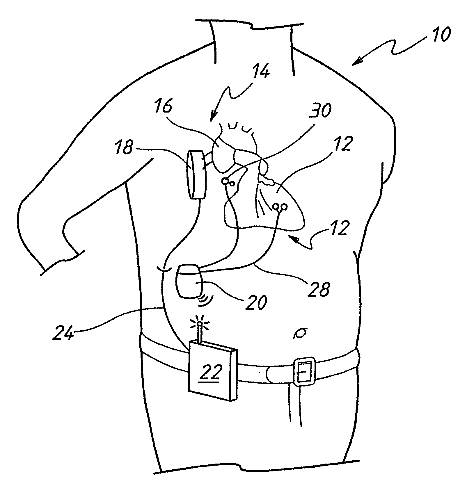
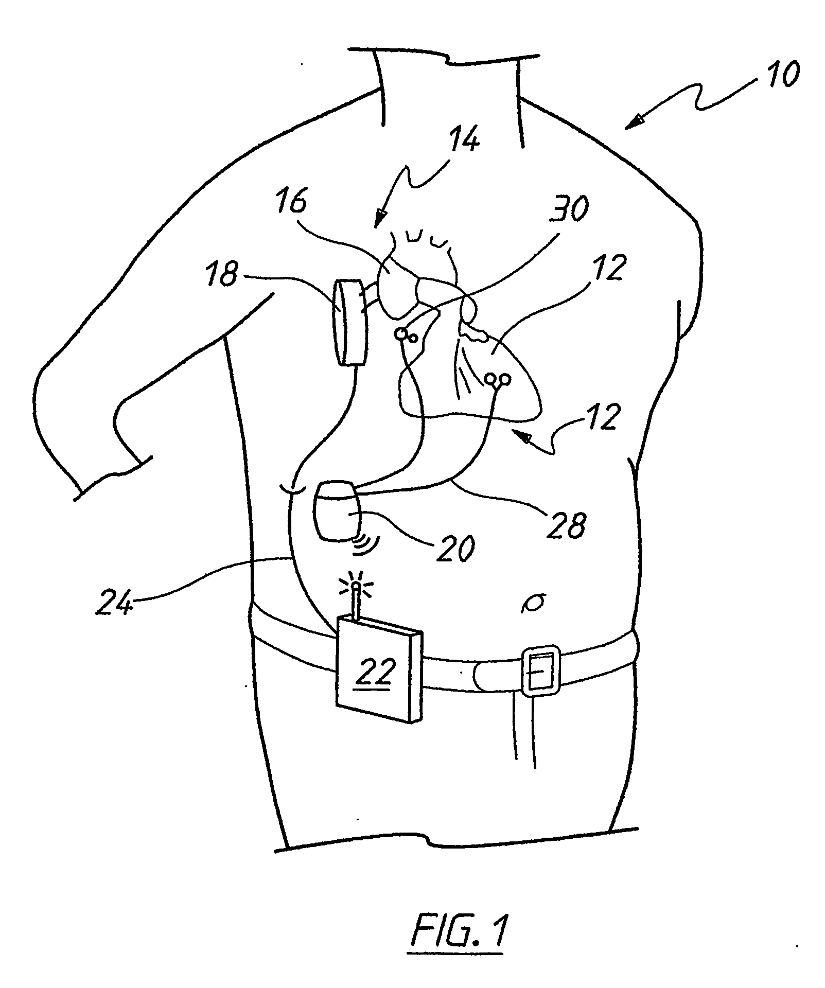
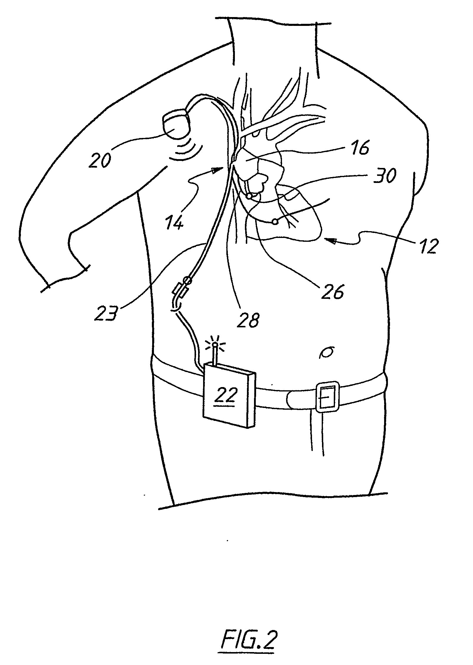
[0053] Sensing is the capability to detect and interpret a patient's native heart electro- and phonocardiograms (ECG's and PCG's respectively). An implanted sensing lead detects the patient's native heart electrical activity and transmits it to the DSPT circuitry. The firmware and / or software within the DSPT unit interprets the patient's R-wave and transmits a signal indicating R-wave detection. An implanted microphone lead detects the patient's native heart sounds and transmits it to the DSPT circuitry. The firmware and / or software within the DSPT unit interprets the patient's heart sounds and transmits a signal indicating S1 and S2 detection.

[0054] Programmability is the capability to allow a physician to adjust the DSPT's sensing and transmitting functions to the patient's individual needs. This is achieved by using a laptop-like device, typically called a progra...


PUM


Abstract

A method of controlling the operation of a pulsatile heart assist device (14) in a patient (10). The method consisting of utilising sounds produced by the heart (12) to control the operation of the heart assist device (14).

Description

TECHNICAL FIELD [0001] The present invention relates to methods and devices for controlling the operation of a pulsatile heart assist device or pacemaker. [0002] The invention has been primarily developed for use in controlling the operation of extra-aortic counter-pulsation heart assist devices, for example as disclosed in the Applicant's International PCT Patent application no. PCT / AU00 / 00654 entitled “Heart assist devices, systems and methods”. However, the invention is also suitable for use in controlling other heart assist devices, including but not limited to, intra-aortic balloons, aortomyoplasty, counter- and co-pulsation devices, or pacemakers or defibrillators or left ventricular assist devices or cardiac cycle monitoring. BACKGROUND OF THE INVENTION [0003] Counterpulsation heart assist devices must be controlled to operate in a predetermined time relationship with the pulsing of a patient's heart. For example, the counter-pulsation heart assist devices disclosed in the Ap...

Claims


Application Information

Patent Timeline
IPC IPC(8): A61N1/362A61B5/352A61M1/10A61N1/365A61N1/37
CPCA61M1/107A61M1/1086A61N1/36514A61N1/36528A61N1/3702A61M1/106A61B5/04012A61B5/0408A61B5/4836A61B7/00A61B5/0006A61B7/04A61B5/316A61B5/25A61M60/274A61M60/289A61M60/531A61M60/191A61M60/468A61M60/161A61M60/88A61M60/178A61M60/569A61M60/515A61M60/873A61N1/36578A61B5/352A61M60/148A61B5/346A61B5/33
Inventor PETERS, WILLIAM SUTTLEPARKIN, RODNEY GORDON
Owner SUNSHINE HEART PTY LTD
Learn More