Adaptive throttle model for air intake system diagnostic

a technology of engine control and adaptive throttle, which is applied in the direction of electrical control, process and machine control, instruments, etc., can solve the problems of complex ability of engine intake flow rationality diagnostic algorithms to effectively monitor and diagnose various problems

Inactive Publication Date: 2007-03-15
GM GLOBAL TECH OPERATIONS LLC
View PDF12 Cites 11 Cited by
  • Summary
  • Abstract
  • Description
  • Claims
  • Application Information

AI Technical Summary

Problems solved by technology

Introduction of new intake system technology onto engines, including for example, variable valve timing systems, and cylinder deactivation systems, has complicated the ability of engi...

Method used


Image

  • Adaptive throttle model for air intake system diagnostic
  • Adaptive throttle model for air intake system diagnostic
  • Adaptive throttle model for air intake system diagnostic

Examples


Embodiment Construction

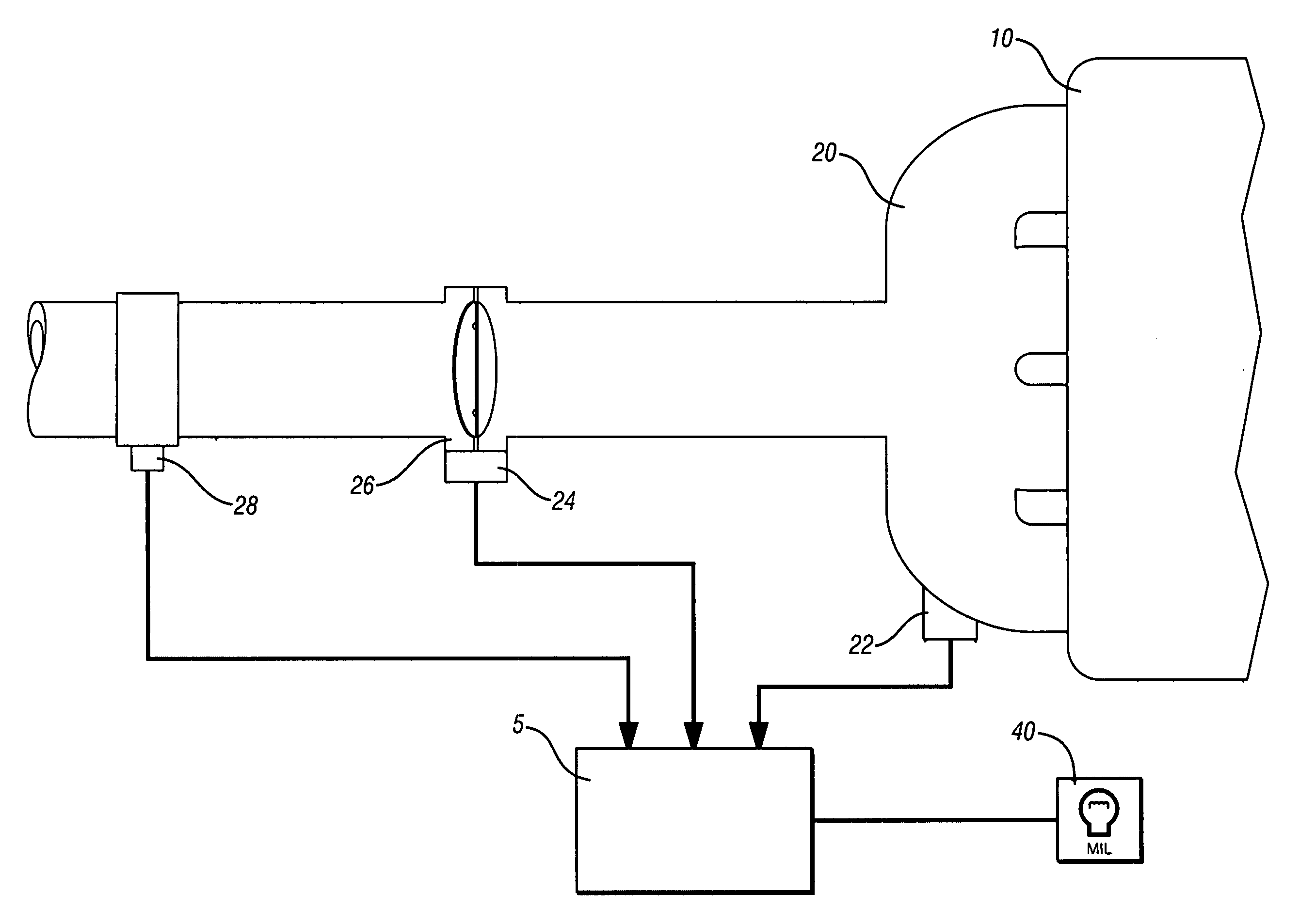
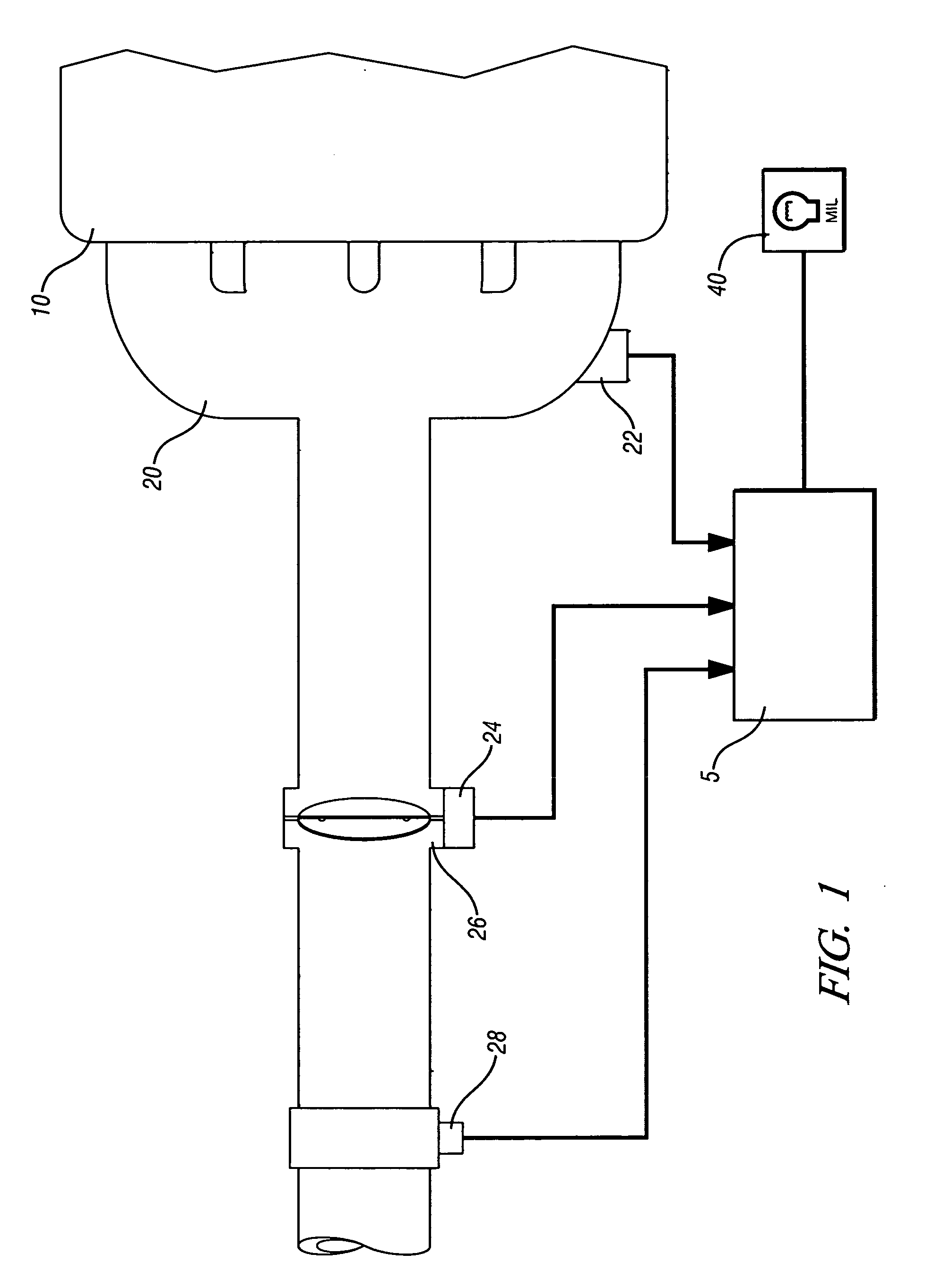
[0025] Referring now to the drawings, wherein the showings are for the purpose of illustrating the invention only and not for the purpose of limiting the same, FIG. 1 shows an internal combustion engine and control system which has been constructed in accordance with an embodiment of the present invention.

[0026] The exemplary engine and control system comprises a conventional four-cycle internal combustion engine 10 controlled by an electronic controller 5. The engine 10 includes a plurality of reciprocating pistons attached to a crankshaft, which is operably attached to a vehicle driveline. The exemplary engine includes an air intake system including an inlet, an air filter, and duct work channeling intake air to the throttle 26. A mass air flow sensor (MAF) 28 is preferably employed to measure air flow during ongoing operation, and may additionally provide intake air temperature (IAT). The throttle 26 comprises a known device having a rotatable throttle blade mounted on a shaft, ...


PUM


Abstract

A method and system to optimize values of a plurality of calibration discharge coefficients useable in a computer program operable to estimate mass air flow into an internal combustion engine having an air intake system comprising a throttle body and a plurality of sensors is presented. This includes collecting engine operation data points, including throttle position. Discharge coefficients are calculated, one for each engine operation data point. The discharge coefficients are partitioned based upon throttle position. Calibration discharge coefficients are calculated for each partitioned plurality of discharge coefficients. This includes circumscribing each calibration discharge coefficient based upon predetermined thresholds. This further includes monitoring and collecting input signals correlatable to airflow from the sensors during ongoing engine operation, preferably comprising throttle position, manifold pressure, intake air temperature, and, atmospheric pressure.

Description

TECHNICAL FIELD [0001] This invention pertains generally to diagnostic systems for internal combustion engine control systems, and more specifically to an adaptive model for an engine control diagnostic system. INCORPORATION BY REFERENCE [0002] Applicant incorporates by reference commonly assigned U.S. Pat. No. 6,701,282 B2, issued to Ting, et al., and entitled Fault Identification Diagnostic for Intake System Sensors, in that the fault identification system for an air intake system need not be fully described in detail herein. BACKGROUND OF THE INVENTION [0003] Vehicle manufacturers are required to produce vehicles having on-board diagnostic systems which monitor various engine, powertrain, and vehicle systems and identify various malfunctions that lead to discernible increases in emissions. One such diagnostic system comprises an engine intake flow rationality diagnostic algorithm, which has been implemented to monitor measurable parameters which contribute to determining flow of ...

Claims


Application Information

Patent Timeline
IPC IPC(8): G06F17/00F02D11/10F02M51/00
CPCF02D41/0002F02D41/187F02D41/22Y02T10/42F02D41/2451F02D2200/0404F02D2200/703F02D41/2432Y02T10/40
Inventor TING, THOMAS L.WALKER, BRUCE K.
Owner GM GLOBAL TECH OPERATIONS LLC
Why Eureka
Try Eureka