Method of casting components with inserts for noise reduction

a technology of inserts and casting components, applied in the direction of rotors, foundry patterns, foundry moulding apparatuses, etc., can solve problems such as contributing to rider discomfort, and achieve the effect of preventing bonding

Active Publication Date: 2007-03-22
GM GLOBAL TECH OPERATIONS LLC
View PDF78 Cites 49 Cited by
  • Summary
  • Abstract
  • Description
  • Claims
  • Application Information

AI Technical Summary

Benefits of technology

[0005] The invention provides a method for manufacturing a powertrain component enclosure member, including the steps of: (A) positioning at least one insert into a mold, wherein the insert is provided with a coating to prevent bonding between the insert and the casting material; and (B) casting a wall of the powertrain component enclosure member in the mold around the insert such that a major portion of the insert is substantially non-bonded with the casting material to provide a proper interfacial boundary with the casting material for damping noise.
[0007] With a portion of each tab bonded with the wall, corrosion-causing exterior elements are prevented from reaching the interfacial boundary.
[0008] The insert may be a flat or curved laminar component, or it may be a component having a large surface area, such as a bundle of wires, etc., which would provide greater surface area for interfacial boundaries, thus increasing damping.
[0009] The invention has been demonstrated for grey iron cast around a steel insert, however, a similar effect should be obtained if an insert is cast into aluminum or magnesium alloys. Like the cast iron / steel insert arrangement, adhesion of the cast structure to the insert must be avoided by use of a barrier coating, or by selection of an insert material that is not “wet” (i.e. melted to cause bonding) by the casting material. An aluminum insert could be used instead of steel, as long as it doesn't dissolve and has a higher melting point than the cast metal.

Problems solved by technology

Vehicle engine noise transmitted to the passenger compartment of the vehicle contributes to rider discomfort.

Method used


Image

  • Method of casting components with inserts for noise reduction
  • Method of casting components with inserts for noise reduction
  • Method of casting components with inserts for noise reduction

Examples


Embodiment Construction

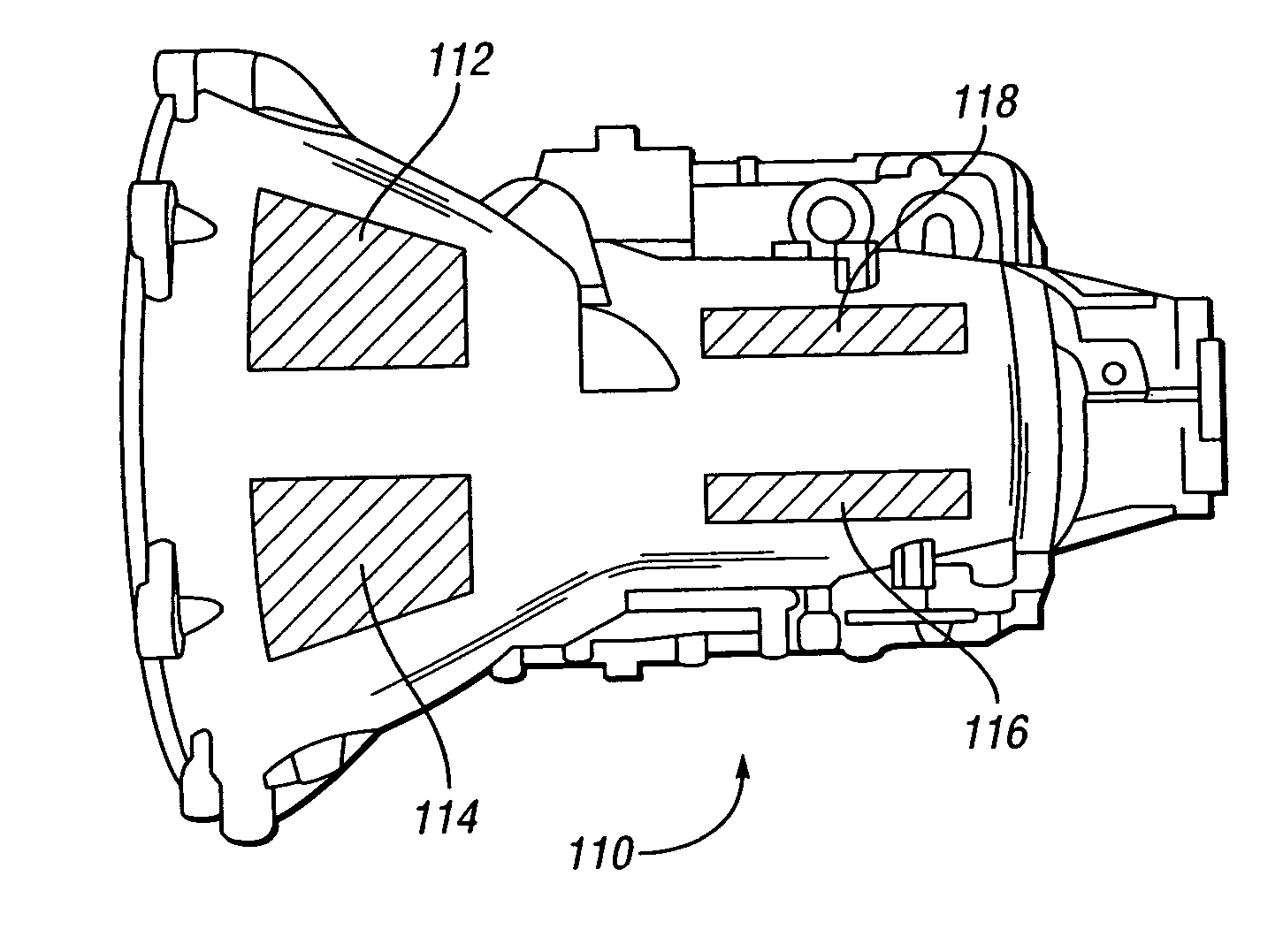
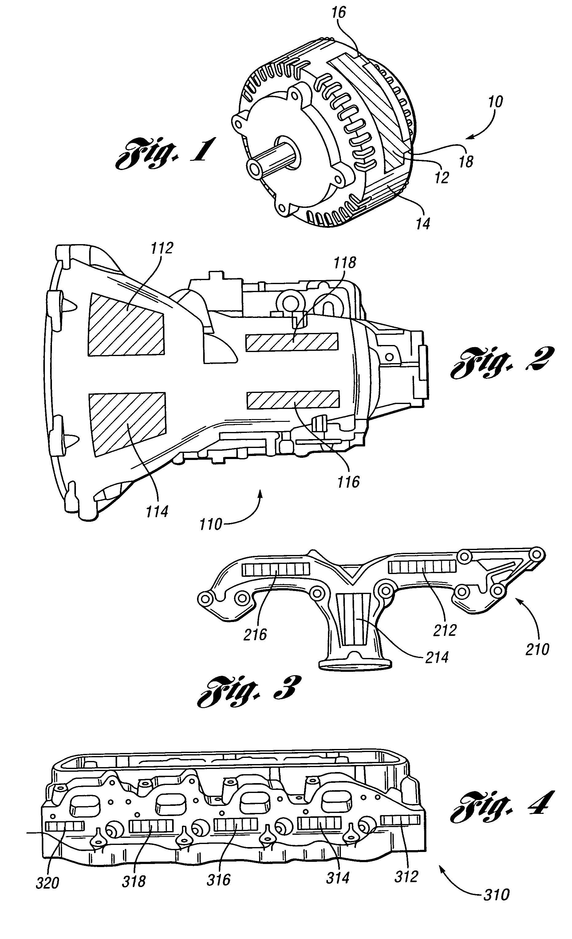
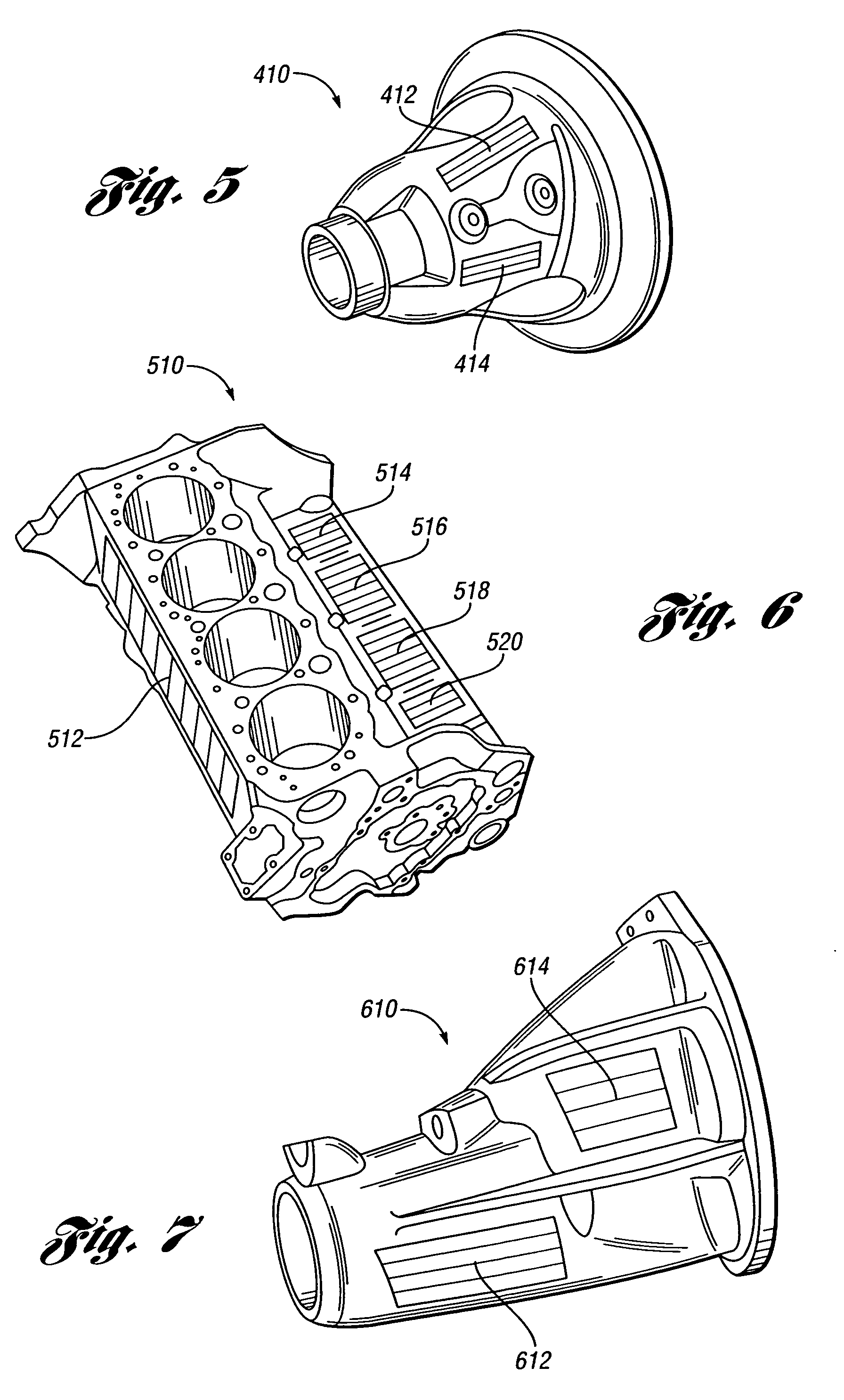
[0019] The invention provides a method for manufacturing a powertrain component enclosure member, including the steps of: (A) positioning at least one insert into a mold, wherein the insert is provided with a coating to prevent bonding between the insert and the casting material; and (B) casting a wall of the powertrain component enclosure member in the mold around the insert such that a major portion of the insert is substantially non-bonded with the casting material to provide a proper interfacial boundary with the casting material for damping.

[0020] Preferably, the insert is supported within the mold cavity by a non-coated tab, as described in the above-referenced United Sates Provisional Application Ser. No. 60 / 717,310, filed Sep. 15, 2005, entitled “Bi-Metal Disc Brake Rotor and Method of Manufacturing”, commonly assigned with the present application, teaches a method for manufacturing a friction damped disc brake rotor, including the steps of: (A) positioning at least one ins...


PUM

PropertyMeasurementUnit
objectionable noiseaaaaaaaaaa
viscoelasticaaaaaaaaaa
transmissionaaaaaaaaaa

Abstract

The invention provides a method for manufacturing a powertrain component enclosure member, including the steps of: (A) positioning at least one insert into a mold, wherein the insert is provided with a coating to prevent bonding between the insert and the casting material; and (B) casting a wall of the powertrain component enclosure member in the mold around the insert such that a major portion of the insert is substantially non-bonded with the casting material to provide a proper interfacial boundary with the casting material for damping.

Description

CROSS-REFERENCE TO RELATED APPLICATION [0001] This application claims the benefit of U.S. Provisional Application No. 60 / 718,945, filed Sep. 20, 2005.TECHNICAL FIELD [0002] The present invention relates to a method and apparatus for damping vehicle noise by casting steel inserts into powertrain housing components to provide noise-damping interfaces within the cast components. BACKGROUND OF THE INVENTION [0003] Vehicle engine noise transmitted to the passenger compartment of the vehicle contributes to rider discomfort. In an effort to reduce the transmission of noise from the engine to the passenger compartment, a variety of techniques have been employed, including the use of polymer coatings on engine parts, sound absorbing barriers, and laminated panels having viscoelastic layers. Other noise reducing efforts have included the use of noise reducing engine mount designs, including active engine mounts that employ magnetorheological fluid actuators. While existing noise reducing effo...

Claims


Application Information

Patent Timeline
Patent Type & Authority Applications(United States)
IPC IPC(8): B22C3/00B22C9/10
CPCB22D19/0054B22D19/00
Inventor SCHROTH, JAMES G.HANNA, MICHAEL D.HAMMAR, RICHARD H.DESSOUKI, OMAR S.LOWE, BRENT D.RIEFE, MARK T.SHORT, JEREMY W.VERBRUGGE, MARK W.
Owner GM GLOBAL TECH OPERATIONS LLC
Why Eureka
Try Eureka