
Bearing cap assembly

a technology of bearing caps and assembly parts, applied in the direction of bearings, crankshaft bearings, shafts and bearings, etc., can solve the problems of vibrational forces, unbalanced moments, and due to imbalance forces, so as to reduce imbalance forces and/or eliminate imbalance forces, the effect of less machining

Inactive Publication Date: 2007-03-22
METALDYNE LLC
View PDF2 Cites 4 Cited by
  • Summary
  • Abstract
  • Description
  • Claims
  • Application Information

AI Technical Summary

Benefits of technology

[0008] The purpose of the present invention is to reduce and / or eliminate imbalance forces, such as vibrational and rotational forces, occurring during operation of the engine. The present invention provides a bearing cap assembly having a crankshaft bore and at least one bearing cap. The crankshaft bore connects the crankshaft of the engine to the balance shaft. The bearing cap rigidly supports the balance shaft and allows the balance shaft to rotate to offset the imbalance forces. The bearing cap is compacted and sintered to provide a rigid fit for the balance shaft. As a result, the present invention provides a bearing cap assembly requiring less machining, less material and reduced production and manufacturing costs. Numerous bearing caps may be incorporated into the bearing cap assembly as required to support any number of balance shafts.

Problems solved by technology

In reciprocating piston engines, imbalance forces are produced due to the mass of reciprocating parts.
For instance, movement of cylinders of an engine cause vibrational forces, such as shaking, and unbalanced moments, such as, rotational forces in an opposite direction to the crankshaft.
As a result, the engine carries additional weight reducing fuel efficiency.
In addition, the drilling of the bearing cap must be precise and often results in cracking of the bearing cap assembly.

Method used


Image

  • Bearing cap assembly
  • Bearing cap assembly
  • Bearing cap assembly

Examples


Embodiment Construction

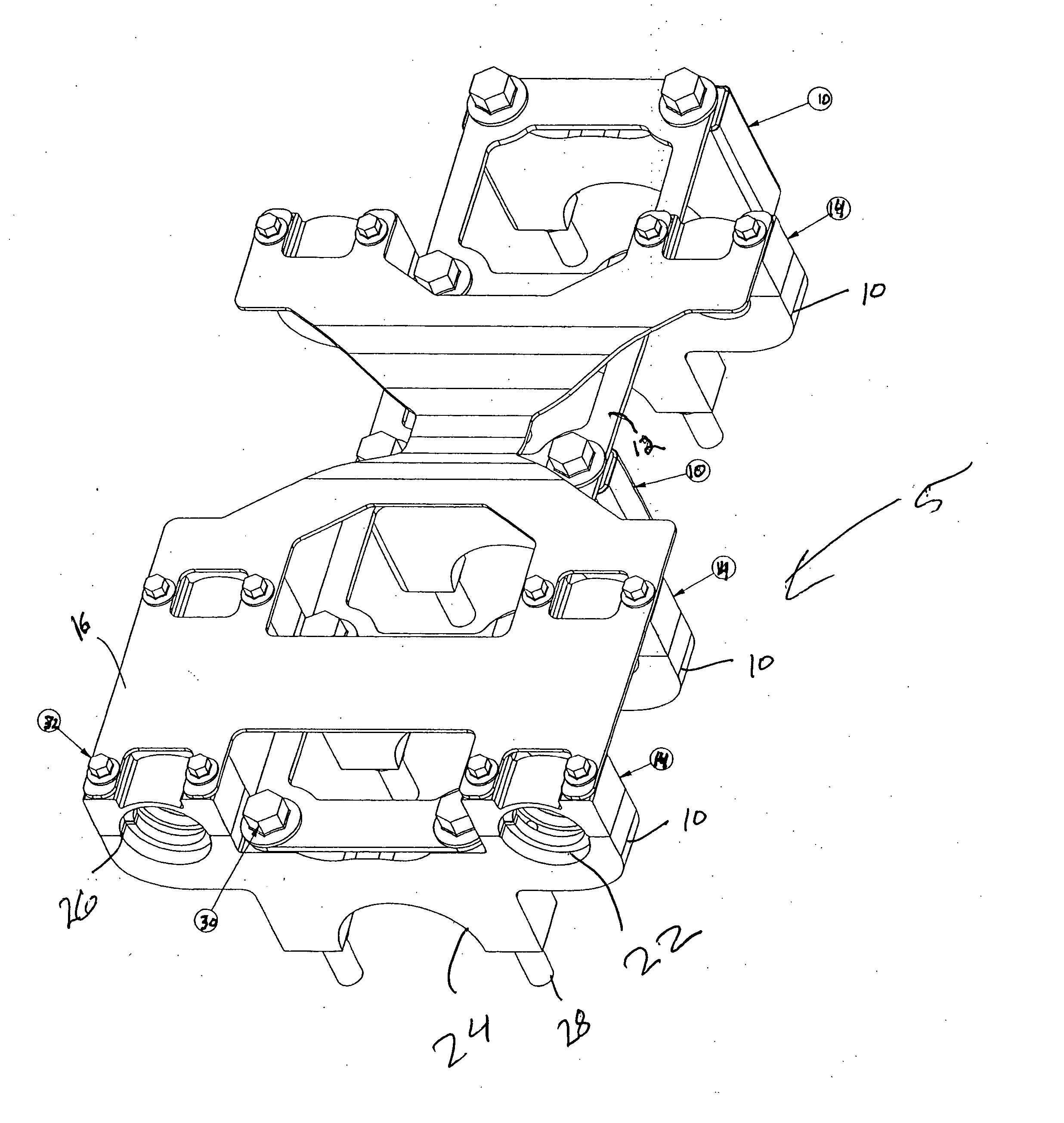
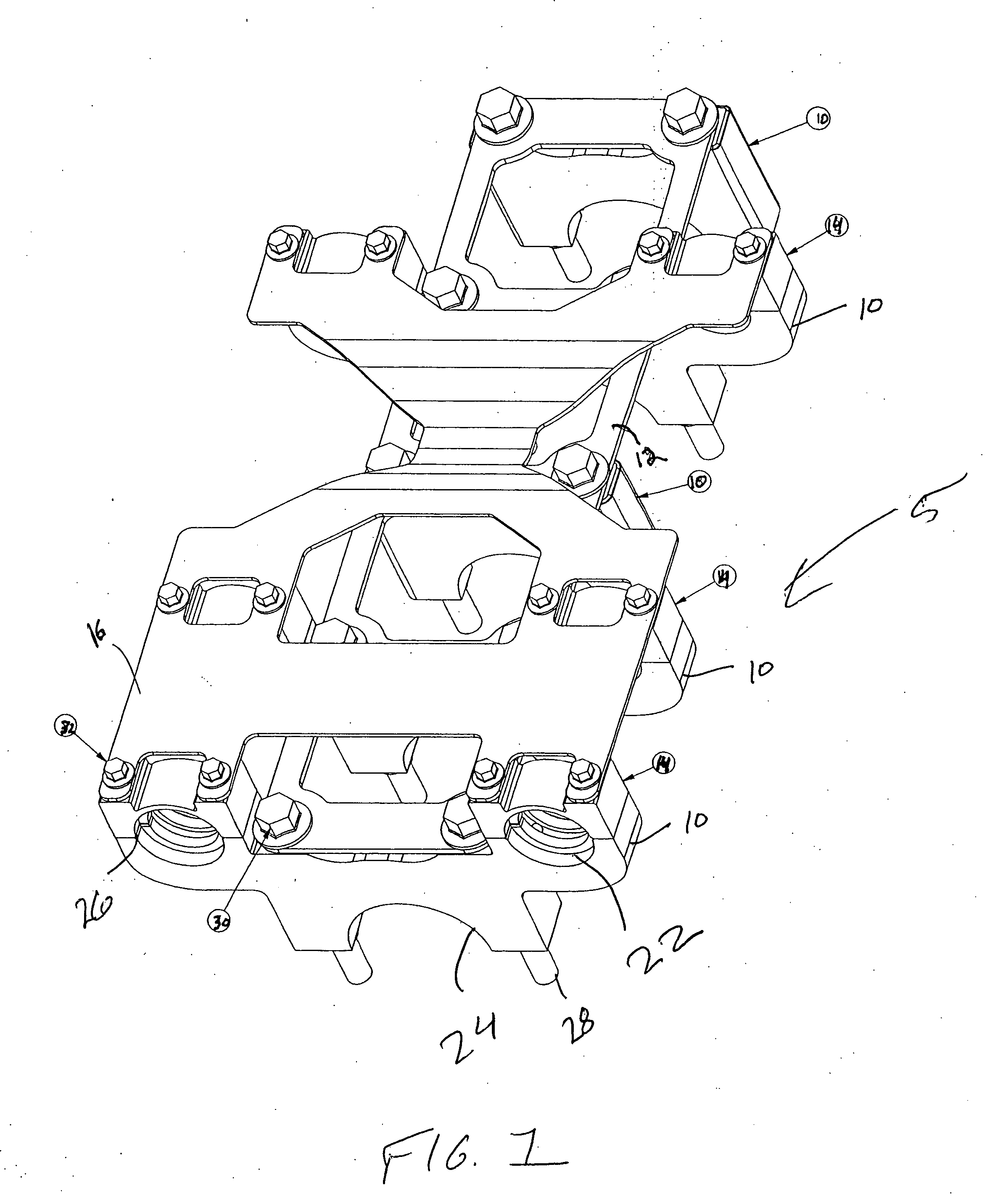
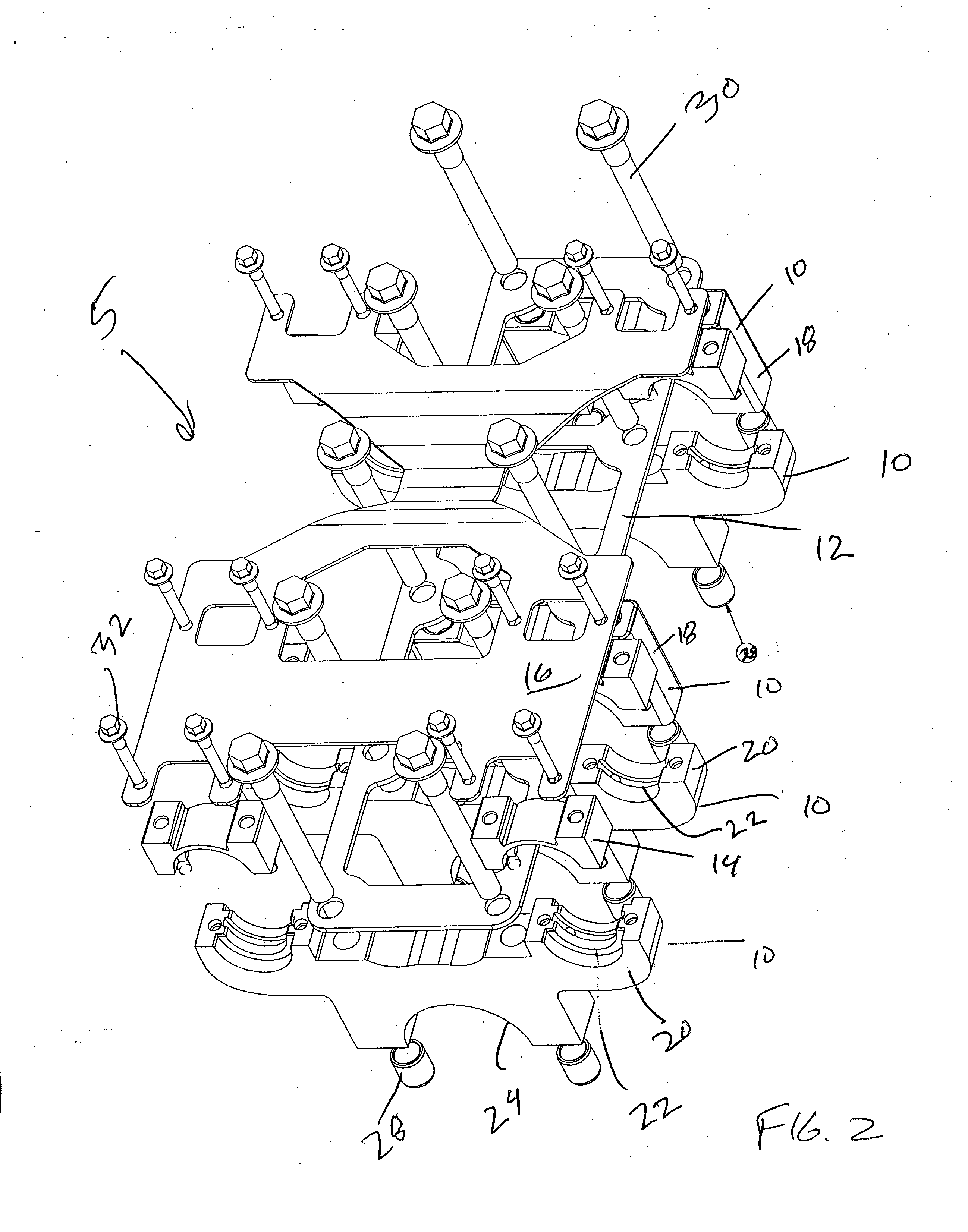
[0015] Referring now to the drawings, which show an embodiment of the invention only for the purpose of illustration and not for purposes of limiting the same, the bearing cap assembly 5 of the present invention generally comprises at least one bearing cap 10 connected to a lower plate 12. The bearing cap 10 is sized and shaped to receive a balance shaft (not shown). FIG. 1 illustrates a perspective view of an embodiment of the bearing cap 10 having two shaft bores. To this end, the bearing cap assembly 5 is sized and shaped for two balance shafts. Of course, the bearing cap assembly 5 of the present invention may be sized and shaped to receive any number of balance shafts without departing from the scope of the present invention.

[0016] Each bearing cap 10 is connected to a corresponding mini-cap 14 and to an upper plate 16. In an embodiment, the upper plate 16 and associated mini-caps 14 are removable from the bearing caps 10. As an example, a fault line 26 extends between the bea...


PUM


Abstract

A bearing cap assembly 5 generally comprising at least one bearing cap 10 having a mini-cap bearing cap 20 and a mini-cap 14. The bearing cap 10 having a shaft bore for receiving a balance shaft and a crankshaft bore for receiving a crankshaft upon connection of the bearing cap assembly 5 to an engine. The bearing cap 10 has a fault line extending between the mini-cap bearing cap 20 and the mini-cap 14 whereby split fracturing the bearing cap 10 along the fault line separates the mini-cap bearing cap 20 from the mini-cap 14. The balance shaft is secured between the mini-cap bearing cap 20 and the mini-cap 14.

Description

CROSS-REFERENCE TO RELATED APPLICATIONS [0001] This application claims priority from U.S. Provisional Patent Application No. 60 / 696,754 filed on Jul. 6, 2005, which is hereby incorporated by reference.BACKGROUND [0002] The present invention relates to a bearing cap assembly for offsetting or eliminating imbalance forces inherent in an engine, and more particularly to a supporting structure for housing balance shafts that to oppose the imbalance forces about a couple moment. [0003] In reciprocating piston engines, imbalance forces are produced due to the mass of reciprocating parts. For instance, movement of cylinders of an engine cause vibrational forces, such as shaking, and unbalanced moments, such as, rotational forces in an opposite direction to the crankshaft. In order to eliminate or offset such forces, a balance shaft having a balancing weight can be provided to counterbalance and / or offset such forces. [0004] In an engine of this type, the balance shaft is supported on a cas...

Claims


Application Information

Patent Timeline
Patent Type & Authority Applications(United States)
IPC IPC(8): F16C9/02
CPCF02F7/0053F02B75/06
Inventor JOHNSON, PETER R.
Owner METALDYNE LLC
Learn More