Method and apparatus for positioning a pipetting device

a pipetting device and positioning technology, applied in the field of pipetting device positioning methods and apparatuses, can solve the problems of difficult to provide such a reliable initialization process, difficult to accurately position the pipetting needle, and difficulty in properly aligning the pipetting needle with the fixed pipetting position, etc., to achieve accurate positioning of the pipetting needle, low cost, and reliable initialization method

Active Publication Date: 2007-03-22
ROCHE DIAGNOSTICS OPERATIONS INC
View PDF13 Cites 33 Cited by
  • Summary
  • Abstract
  • Description
  • Claims
  • Application Information

AI Technical Summary

Benefits of technology

[0033] The main advantage obtained with a method and an apparatus according to the invention is that it makes possible to (a) achieve a reliable initialization method at low cost, because it uses means available in the analyzer for other purposes, namely an excenter mechanism primarily used for performing mixing of liquids by moving the pipetting needle along a circular path, and level detection means which are primarily used for detecting contact of the pipetting needle with a liquid surface during pipetting operations, and to (b) accurately position a pipetting needle in a plurality of pipetting positions.

Problems solved by technology

Even after thorough mechanical adjustment of the position of the pipetting needle during manufacture of the analyzer, the sum of the manufacturing tolerances of the various components of the analyzer and the deformations of the needle with time cause deviations of the position of the pipetting needle and make it difficult to have the pipetting needle properly aligned with the fixed pipetting positions it is expected to be positioned at by a transport device of the automatic pipetting unit.
The task of providing such a reliable initialization process is particularly difficult when the transport device moves the pipetting needle only along a straight line, e.g. in X-direction only, and all pipetting positions are located in that linear path of the motion of the pipetting needle.
A reliable initialization process is even more difficult to achieve when the portion of the pipetting needle which is introduced into a vessel for effecting a pipetting operation is moved along a circular path within the vessel for mixing liquids introduced in that vessel.
Known initialization methods require relatively expensive means.

Method used


Image

  • Method and apparatus for positioning a pipetting device
  • Method and apparatus for positioning a pipetting device
  • Method and apparatus for positioning a pipetting device

Examples


Embodiment Construction

[0184] Preferred embodiments are described hereinafter with reference to the accompanying drawings.

Example of an Analyzer

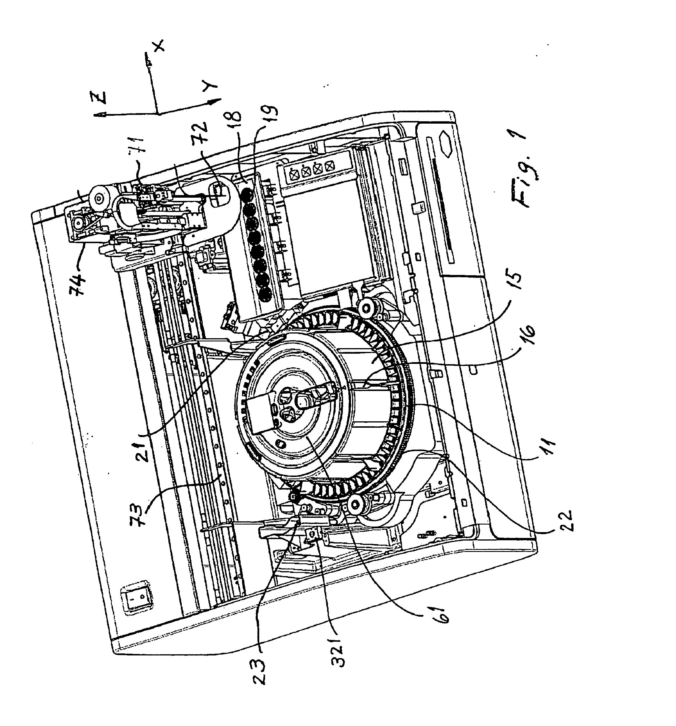
[0185] As shown by FIG. 1 an analyzer according to the invention, e.g. a clinical-chemistry for analyzing sample-reagent mixtures contained in reaction cuvettes. The analyzer shown in FIG. 1 comprises a rotatable conveyor 11 for conveying reaction cuvettes 31 inserted in corresponding cavities of that conveyor along a circular path, at least one array of reaction cuvettes 31, a hollow body 51 (shown in FIG. 14) arranged in the central part of conveyor, a reagent container assembly 61 installed in a cavity 54 of hollow body 51, a sample tube area 18 located adjacent to conveyor 11, an automatic pipetting unit 71, a photometer 21 located adjacent to conveyor 11, and conveyor driving means 22 for rotating conveyor 11.

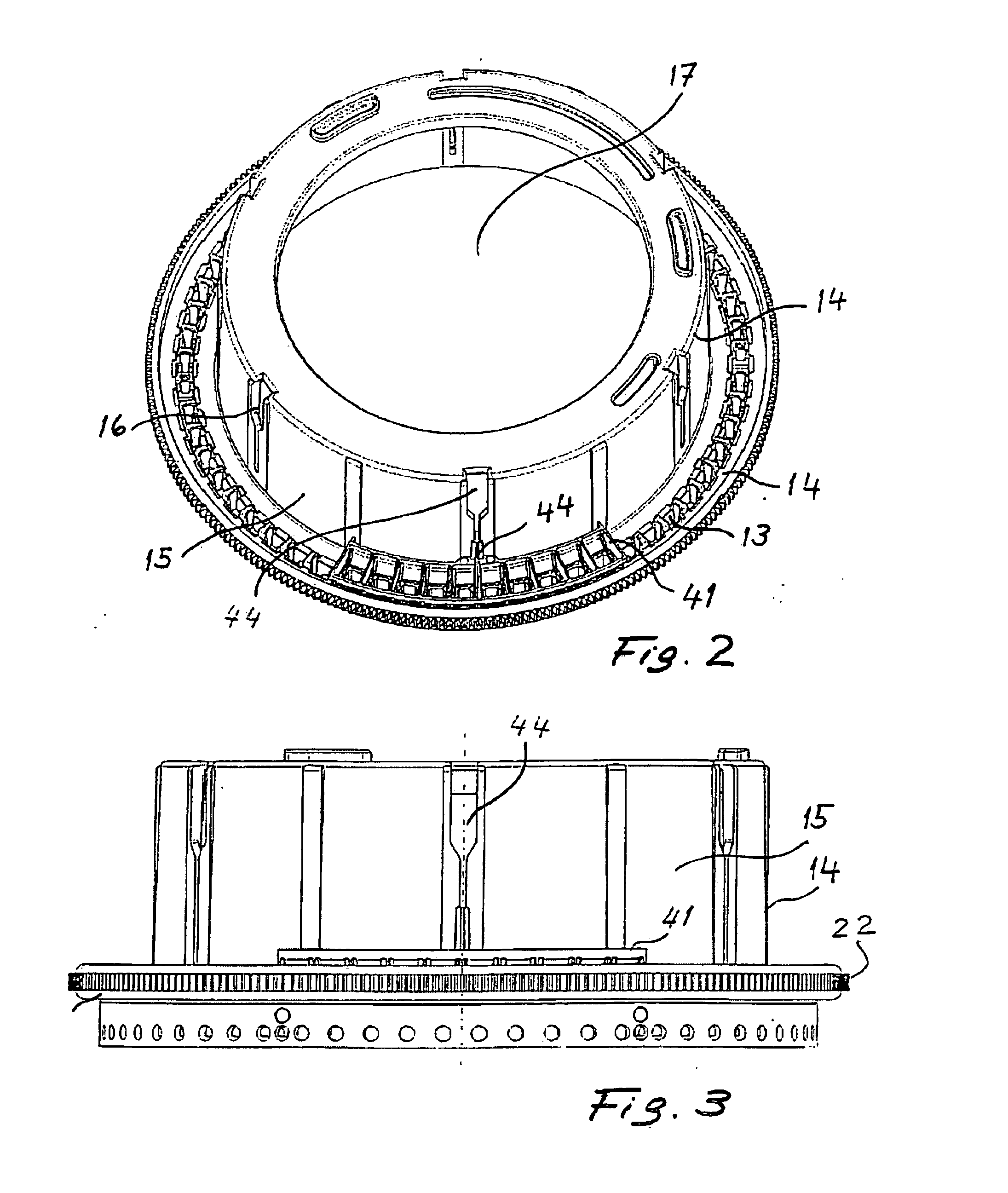
[0186]FIG. 3 shows the rotation axis 25 of conveyor 11.

[0187] Reaction cuvettes 31 inserted in the above mentioned cavities of conveyor 11 are loos...


PUM

PropertyMeasurementUnit
thicknessaaaaaaaaaa
angleaaaaaaaaaa
lengthaaaaaaaaaa

Abstract

A method for determining a reference position for a pipetting needle which is part of an automatic analytical apparatus. The method comprises the following steps: a first measuring step for measuring a first displacement error (ΔX) in a displacement of the pipetting needle effected by a transport device, a first correcting step for correcting the first displacement error (ΔX) by means of a corresponding correction of an angular error (φ) of the initial angular position of the pipetting needle, a second measuring step for measuring a second displacement error (ΔY) in a displacement of the pipetting needle in a second direction (Y-axis) perpendicular to the vertical plane, a second correcting step for correcting the second displacement error (ΔY) by means of a corresponding change (α) of the angular position of the pipetting needle along a circular path, a third measuring step for determining the position of a vertical reference line, and a fourth measuring step for determining the position of a reference point (X0, Y0, Z0) along said reference line,

Description

RELATED APPLICATIONS [0001] This application claims priority to EP 05077157.5 filed Sep. 21, 2005. FIELD OF THE INVENTION [0002] The invention concerns a method according to the preamble of claim 1. The invention further concerns an analyzer that comprises means for carrying out the method according to the invention. BACKGROUND [0003] Automatic analyzers, and in particular clinical chemistry analyzers, comprise an automatic pipetting unit with which pipetting operations are performed in a plurality of fixed positions. Even after thorough mechanical adjustment of the position of the pipetting needle during manufacture of the analyzer, the sum of the manufacturing tolerances of the various components of the analyzer and the deformations of the needle with time cause deviations of the position of the pipetting needle and make it difficult to have the pipetting needle properly aligned with the fixed pipetting positions it is expected to be positioned at by a transport device of the auto...

Claims


Application Information

Patent Timeline
Patent Type & Authority Applications(United States)
IPC IPC(8): G01N35/00
CPCG01N35/1011G01N2035/0491G01N2035/0494Y10T436/12Y10T436/11Y10T436/113332Y10T436/2575
Inventor SIGRIST, ROLF
Owner ROCHE DIAGNOSTICS OPERATIONS INC
Why Eureka
Try Eureka