Injection device with puncture function, method for controlling injection device with puncture function, chemical solution administration device, and method for controlling chemical solution administration device

a technology of injection device and function, which is applied in the directions of catheters, applications, and injection devices with puncture functions, can solve the problems of troublesome taking along all of these units, and achieve the effects of convenient taking along, saving the burden of setting, and being convenient to take along

Active Publication Date: 2007-03-22
PHC HLDG CORP
View PDF16 Cites 72 Cited by
  • Summary
  • Abstract
  • Description
  • Claims
  • Application Information

AI Technical Summary

Benefits of technology

[0047] An injection device with puncture function according to the present invention includes, in a single casing, a cartridge in which a chemical solution is enclosed, and having a needle inserted at a front end thereof; a cartridge holder into which the cartridge is inserted; a reciprocation means for reciprocating the cartridge and the cartridge holder; and an extrusion means for extruding the chemical solution from a rear end of the cartridge toward the needle; wherein the reciprocation means reciprocates the cartridge and, at this time, a motion speed and an amount of motion of the reciprocation means are variable, and puncture by the needle or administration of the chemical solution through the needle is carried out. Therefore, the function of the puncture device for collecting blood and the function of the injection device for administrating the chemical solution are included in the same casing, thereby realizing an injection device with puncture function which can be easily taken along.
[0048] Further, according to the present invention, since the needle for collecting blood and the reciprocation means for reciprocating the needle are commoditized, miniaturizat...

Problems solved by technology

In the conventional administration of insulin, however, since the puncture unit 1, the measurement unit 4, and th...

Method used


Image

  • Injection device with puncture function, method for controlling injection device with puncture function, chemical solution administration device, and method for controlling chemical solution administration device
  • Injection device with puncture function, method for controlling injection device with puncture function, chemical solution administration device, and method for controlling chemical solution administration device
  • Injection device with puncture function, method for controlling injection device with puncture function, chemical solution administration device, and method for controlling chemical solution administration device

Examples


embodiment 1

[Embodiment 1]

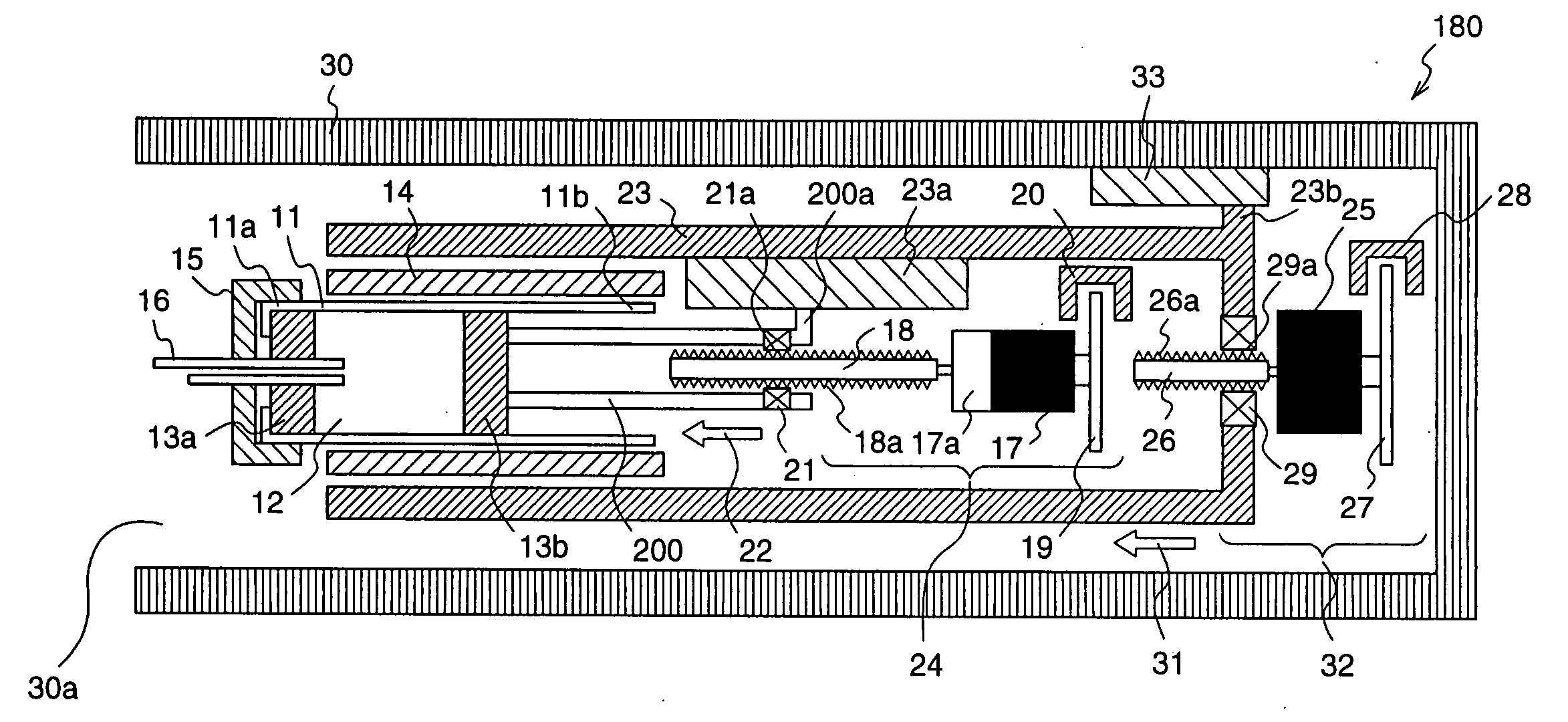
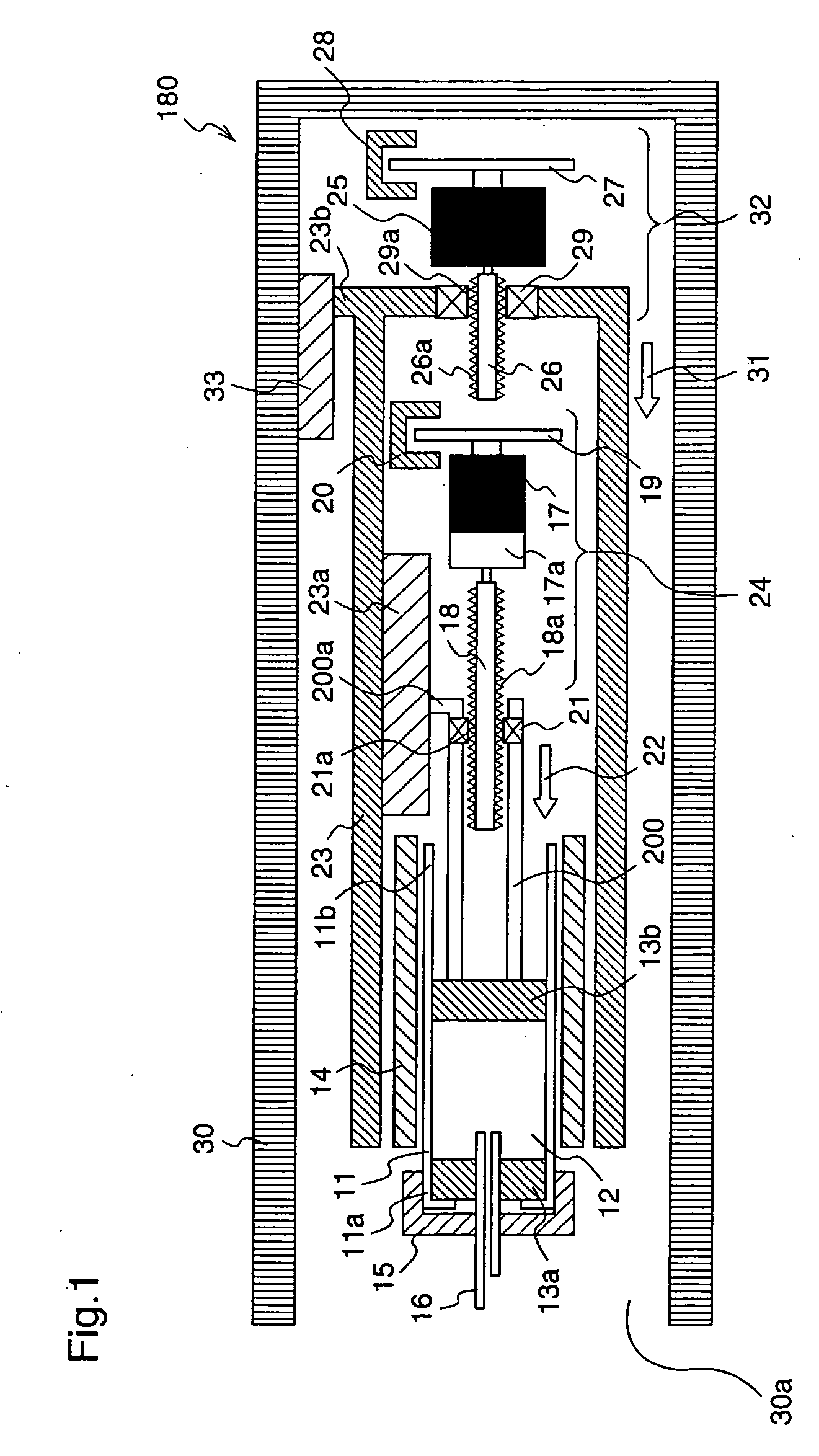
[0073]FIG. 1 is a cross-sectional view illustrating an injection device with puncture function according to a first embodiment of the present invention.

[0074] With reference to FIG. 1, reference numeral 11 denotes a cylindrical cartridge in which insulin 12 adopted as an example of a chemical solution is enclosed, and rubber stoppers 13a and 13b are inserted at a front end 11a and a rear end 11b of the cartridge 11, respectively.

[0075] Reference numeral 14 denotes a cartridge holder into which the cartridge 11 is inserted. The cartridge 11 is attached to the cartridge holder 14, and a circular cap 15 is attached to the front end of the cartridge 11. The cartridge 11 and the cap 15 are detachable from the cartridge holder 14. A hollow needle 16 comprising metal is set in approximately the center of the cap 15. A root side of the needle 16 penetrates the stopper 13a that is inserted at the front end 11a of the cartridge 11, and reaches the insulin 12.

[0076] Reference ...

embodiment 2

[Embodiment 2]

[0136]FIG. 5 is a perspective view illustrating an injection device with puncture function 170 according to a second embodiment of the present invention, with its upper cover being opened. In FIG. 5, the same reference numerals as those used for the first embodiment denote the same elements, and therefore, repeated description is not necessary.

[0137] With reference to FIG. 5, reference numeral 11 denotes a cartridge in which insulin 12 is enclosed, and this cartridge 11 is inserted into a cartridge holder 71. Further, reference numeral 16 denotes a needle inserted at a front end of the cartridge 11.

[0138] Reference numeral 72 denotes a first motor as a component of an extrusion means 73. Rotation of the first motor 72 is transmitted to a main axis 75 through a deceleration gear 74. The main axis 75 is connected to a first shaft 77 through transmission gears 76a, 76b, 76c. The first shaft 77 is connected to a first nut 79 through an elastic extension member 78. Furthe...

embodiment 3

[Embodiment 3]

[0155]FIG. 8 is a cross-sectional view of an injection device with puncture function 190 according to a third embodiment of the present invention.

[0156] In the first and second embodiments, the injection device with puncture function is driven by two motors, such as the first motor 17 and the second motor 25 for the injection device 180 of the first embodiment, or the first motor 72 and the second motor 82 for the injection device 170 of the second embodiment. However, the injection device with puncture function 190 according to the third embodiment is constituted such that a coil and a magnet are used instead of the second motor that is one of the two motors, and a driving force is applied to the reciprocation means by the coil and the magnet.

[0157] The puncture and blood-collecting operation of injection device with puncture function 190 constituted as described above have the following characteristics. [0158] (Characteristics of Puncture and Blood-Collecting Opera...


PUM


Abstract

An injection device with puncture function includes, in a single casing 30, a cylindrical cartridge 11 in which insulin 12 is enclosed, a cartridge holder 14 to which the cartridge 11 is inserted, a needle 16 inserted at a front end 11a of the cartridge 11, a reciprocation means 32 for reciprocating the cartridge 11 toward the needle 16, and an extrusion means 23 for extruding the insulin 12 from a rear end11b of the cartridge 11 toward the needle 16, and the motion speed and the motion amount of the reciprocation means 32 are made variable.

Description

FIELD OF THE INVENTION [0001] The present invention relates to an injection device with puncture function, a method for controlling the injection device with puncture function, a chemical solution administration device, and a method for controlling the chemical solution administration device. BACKGROUND OF THE INVENTION [0002] A diabetic patient measures his / her blood glucose level periodically, and injects insulin on the basis of the blood glucose level to keep a normal blood glucose level. Conventionally, in order to measure blood glucose level, a small amount of blood is collected from a finger tip or the like of a patient using a puncture unit, and next, the blood glucose level of the collected blood is measured using a measurement unit, and thereafter, insulin is injected into the patient according to the measured blood glucose level using an injection unit. [0003] More specifically, as shown in FIG. 17, initially a puncture needle port 2 of a puncture unit 1 is applied to a fi...

Claims


Application Information

Patent Timeline
IPC IPC(8): A61M1/00
CPCA61B5/1411A61B5/14532A61M5/14566A61M2230/201A61M2005/1402A61M2205/52A61M5/1723A61B5/150022A61B5/150167A61B5/150175A61B5/150213A61B5/150358A61B5/150389A61B5/150503A61B5/150954A61B5/15113A61B5/15123A61B5/1513A61B5/15132A61B5/1519A61B5/15194A61B5/157A61M5/20A61M5/24A61M2005/2013A61M2005/206
Inventor IIO, TOSHIAKIAMANO, YOSHINORI
Owner PHC HLDG CORP
Why Eureka
Try Eureka