Adjustable hay rake

a hay rake and adjustable technology, applied in the field of agricultural hay rake devices, can solve the problems of insufficient support of a long vertical spring arrangement, limited length, strength, and functionality of the long rake arms, and achieve the effects of less rigidity, minimal structural modifications, and more weight reduction

Active Publication Date: 2007-03-29
KUHN NORTH AMERICA
View PDF15 Cites 12 Cited by
  • Summary
  • Abstract
  • Description
  • Claims
  • Application Information

AI Technical Summary

Benefits of technology

[0011] For example, an embodiment of the present invention can provide a hay rake with rake arms which are “floated” while in operating position by using a substantially horizontal oriented spring, shock or cushion, allowing more weight reduction to be applied to the rake arm with minimal structural modifications. This horizontal spring can be longer with less stiffness than a vertical spring, providing a wider range of motion for the rake arms, with more even support during ...

Problems solved by technology

These long rake arms can be heavy and cumbersome both in operation and in transport.
One disadvantage of a vertical style spring or shock is that it is somewhat limited to its length, strength, and functionality.
This is because the axle and wagon assembly at the spring mounting point is generally horizontal, and cannot adequately support a long vertical spring arrangement.
The result is that vertical springs are typically short, requiring a stiff spring construction and a short effective r...

Method used


Image

  • Adjustable hay rake
  • Adjustable hay rake
  • Adjustable hay rake

Examples


Embodiment Construction

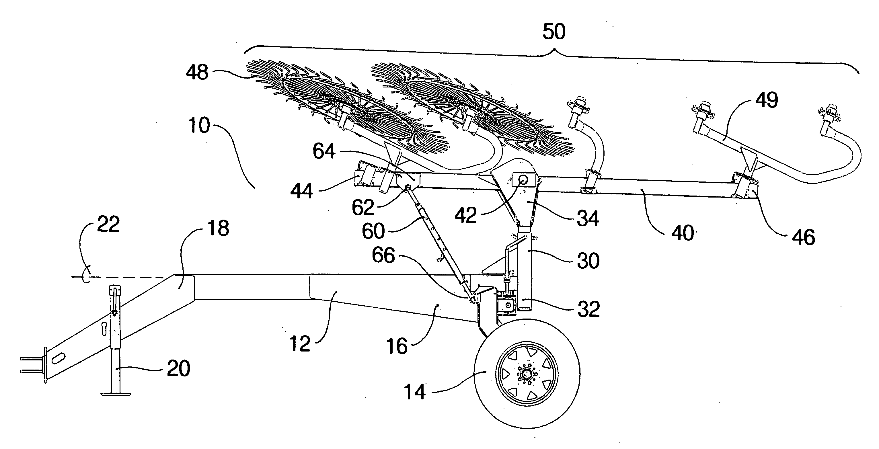
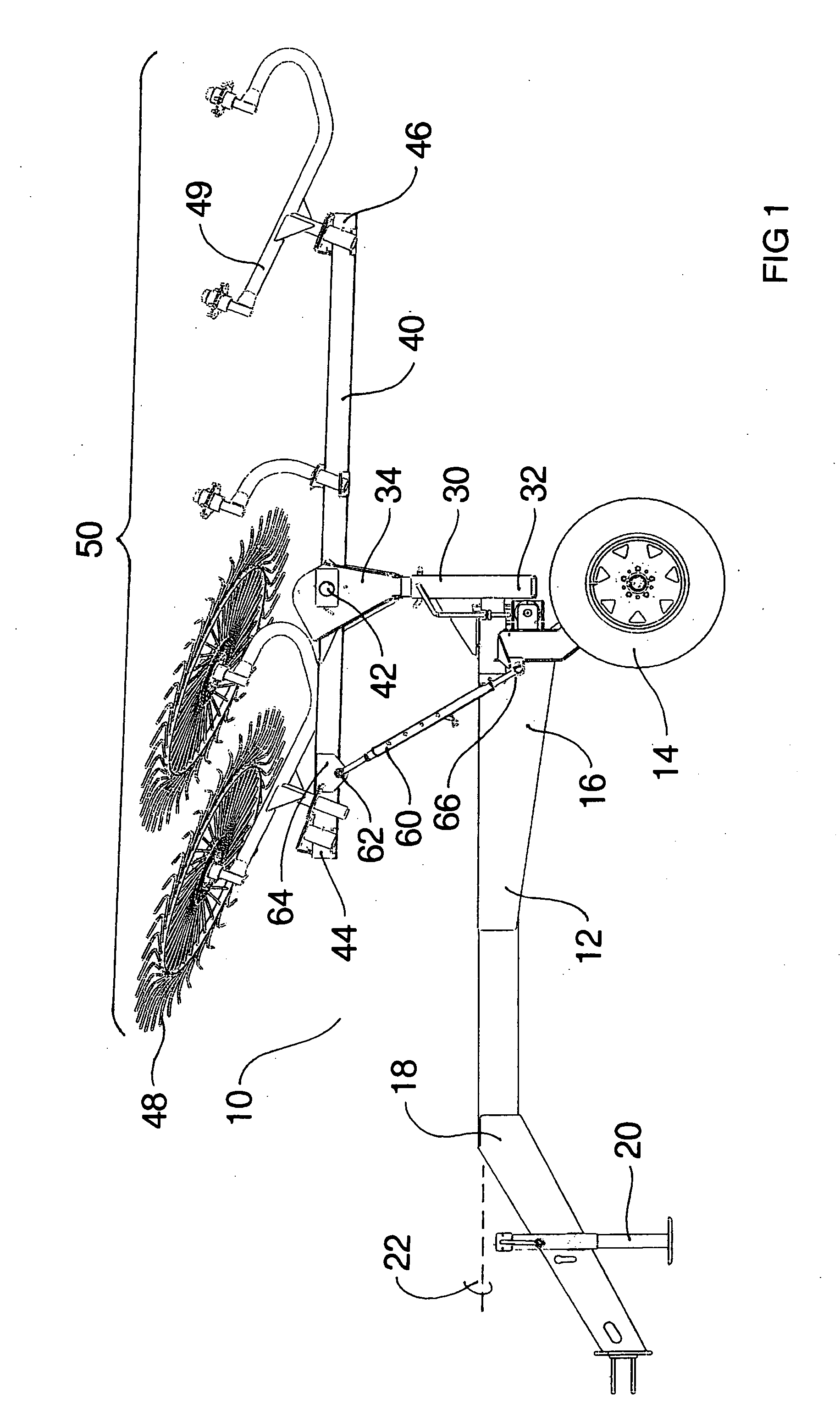
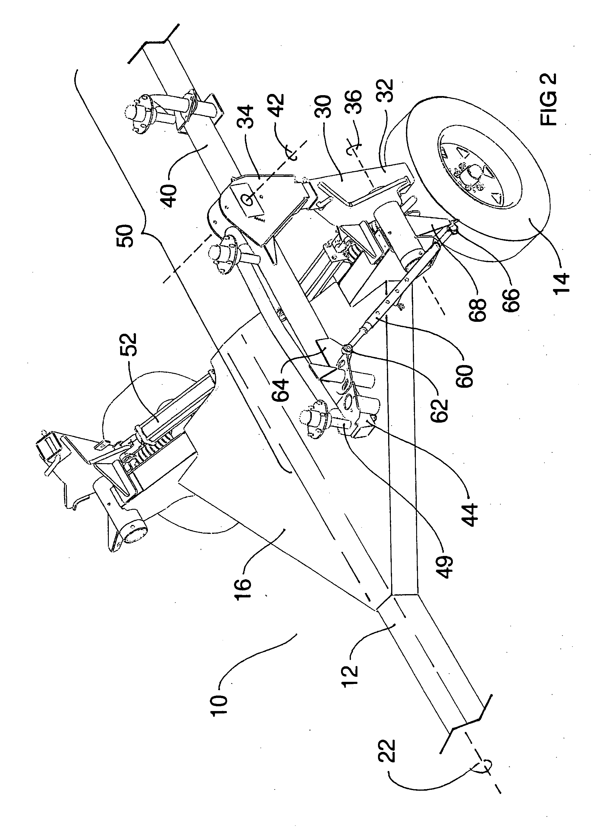
[0019] With reference to FIGS. 1-4, a non-limiting hay rake apparatus is generally designated by the reference number 10. The hay rake 10 includes a wheeled cart 12, which can further include tires 14, a frame 16, a tongue hitch 18 for attachment to a tractor or towing means (not shown) and a jackstand 20. The tongue can be oriented along a longitudinal axis 22, which is generally inline with the direction of travel. A folding arm 30 includes a first end 32, and a second end 34. The first end 32 of the folding arm 30 is attached, or mechanically coupled, to the wheeled cart 12 at a pivot axis 36. The second end 34 of the folding arm 30 is attached, or mechanically coupled, to a rake arm 40 at a rake arm axis 42.

[0020] The rake arm 40 has a leading end 44 and a trailing end 46. A plurality of tine rake wheels 48 are attached to rake wheel arms 49 along the length of the rake arm 40 to rake the hay materials when in operation. The combination of the folding arm 30, the rake arm 40, t...


PUM


Abstract

A carted hay rake is disclosed for raking cut crops into a windrow. The hay rake can include a wheeled cart, rake arms, and tine rake wheels. The rake arms are attached to a rake arm pivot, and can be extendable to a horizontal working position and retractable to a transport position. A positioning arm is utilized to change the angle of the rake arm between the working and transport position. An assist spring can help neutralize the weight of the rake arm while in the working position. The assist spring can be positioned horizontally.

Description

BACKGROUND OF THE INVENTION [0001] 1. Field of the Invention [0002] This invention relates to an agricultural hay rake device. [0003] 2. Discussion of the Background [0004] Agricultural hay rakes, specifically carted or folding hay rakes are used to form windrows from cut crops, including hay, straw and grasses. It is a typical agricultural process to cut these crops, rake or merge them into windrows where additional drying may occur, collect and store the crops, and subsequently feed the crops to livestock. [0005] Modern power equipment for raking cut forage employs rotating tined wheels and particularly banks of rotating tined wheels that are moved through a field of cut forage to form windrows. These banks of wheel rakes can be quite wide to reduce both the time and number of passes required to rake a field. Because of the wide widths employed by hay rakes, they typically have pivot points on each rake arm in order to fold to a narrower width for transport. Wide rakes thereby off...

Claims


Application Information

Patent Timeline
IPC IPC(8): A01D78/00
CPCA01D78/144A01D78/1014
Inventor CICCI, GEORGEBASSETT, BILL
Owner KUHN NORTH AMERICA
Why Eureka
Try Eureka