Microbolometer IR Focal Plane Array (FPA) with In-Situ Micro Vacuum Sensor and Method of Fabrication

a micro vacuum sensor and microbolometer technology, applied in the field of microbolometer ir focal plane arrays (fpas), can solve the problems of large resistance variability, small and achieve large temperature increase, large resistance variability, and poor heat transfer

Active Publication Date: 2007-03-29
TELEDYNE SCI & IMAGING
View PDF5 Cites 28 Cited by
  • Summary
  • Abstract
  • Description
  • Claims
  • Application Information

AI Technical Summary

Benefits of technology

[0008] This is accomplished by realizing that the IR sensor microbolometer pixel element itself may be used as a vacuum sensor. The bolometer pixel can be used as a vacuum sensor because the application of an electrical signal to the resistive element heats the bolometer material thereby producing a variable resistance related to vacuum level. The degree of variability for a given material depends on the efficiency of heat transfer from the material to the surrounding environment. In a good vacuum, heat transfer is poor, and thus heat will be retained in the material to produce a relatively large temperature increase and the resistance variability will be large. In a poor vacuum, heat is readily transferred to the environment and the temperature rise will be relatively small and thus resistance variability will be small. Consequently, the variable resistance magnitude can be readout to determine the vacuum level.

Problems solved by technology

In a good vacuum, heat transfer is poor, and thus heat will be retained in the material to produce a relatively large temperature increase and the resistance variability will be large.
In a poor vacuum, heat is readily transferred to the environment and the temperature rise will be relatively small and thus resistance variability will be small.

Method used


Image

  • Microbolometer IR Focal Plane Array (FPA) with In-Situ Micro Vacuum Sensor and Method of Fabrication
  • Microbolometer IR Focal Plane Array (FPA) with In-Situ Micro Vacuum Sensor and Method of Fabrication
  • Microbolometer IR Focal Plane Array (FPA) with In-Situ Micro Vacuum Sensor and Method of Fabrication

Examples


Embodiment Construction

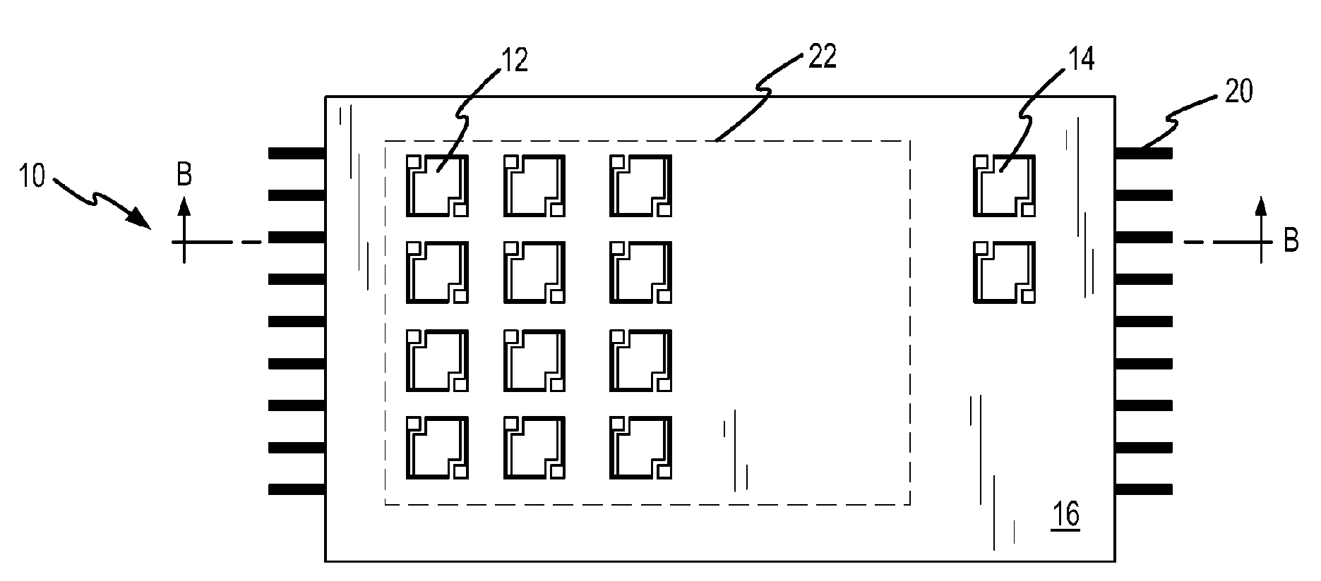
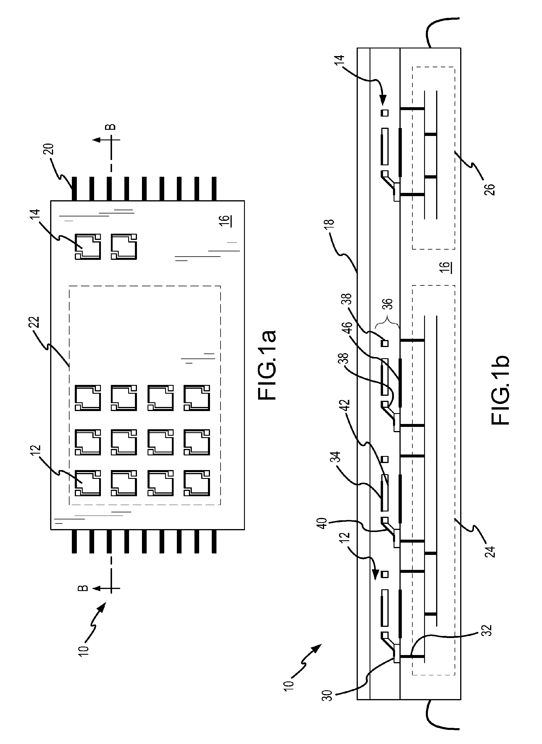
[0021] A microbolometer IR FPA is provided with in-situ vacuum sensing capability by realizing that the IR sensor microbolometer pixel element itself may be used as a vacuum sensor. The application of an electrical signal to the resistive element heats the bolometer material (“Joule heating”) thereby producing a variable resistance related to vacuum level. The degree of variability for a given material depends on the efficiency of heat transfer from the material to the surrounding environment. In a good vacuum, heat transfer is poor, and thus heat will be retained in the material to produce a relatively large temperature increase and the resistance variability will be large. In a poor vacuum, heat is readily transferred to the environment and the temperature rise will be relatively small and thus resistance variability will be small. Consequently, the variable resistance magnitude can be readout to determine the vacuum level.

[0022] In an exemplary embodiment, a microbolometer IR FP...


PUM


Abstract

A microbolometer IR FPA is provided with in-situ vacuum sensing capability by realizing that the IR sensor microbolometer pixel element itself may be used as a vacuum sensor. The application of an electrical signal to the resistive element heats the bolometer material thereby producing a variable resistance related to vacuum level. The degree of variability for a given material depends on the efficiency of heat transfer from the material to the surrounding environment. In a good vacuum, heat transfer is poor, and thus heat will be retained in the material to produce a relatively large temperature increase and the resistance variability will be large. In a poor vacuum, heat is readily transferred to the environment and the temperature rise will be relatively small and thus resistance variability will be small. Consequently, the variable resistance magnitude can be readout to determine the vacuum level.

Description

FIELD OF THE INVENTION [0001] This invention relates to microbolometer IR focal plane arrays (FPAs) and more specifically to the integration of a micro vacuum sensor with the IR FPA. DESCRIPTION OF THE RELATED ART [0002] Infrared (IR) detectors are often utilized to detect fires, overheating machinery, planes, vehicles, people, and any other objects that emit thermal radiation. Infrared detectors are unaffected by ambient light conditions or particulate matter in the air such as smoke or fog. Thus, infrared detectors have potential use in night vision and when poor vision conditions exist, such as when normal vision is obscured by smoke or fog. IR detectors are also used in non-imaging applications such as radiometers, gas detectors, and other IR sensors. [0003] Infrared detectors generally operate by detecting the differences in thermal radiance of various objects in a scene. That difference is converted into an electrical signal which is then processed to produce an output related...

Claims


Application Information

Patent Timeline
Patent Type & Authority Applications(United States)
IPC IPC(8): G01J5/02
CPCG01L21/12G01J5/20
Inventor DEWAMES, ROGER E.WALDROP, JAMES R.
Owner TELEDYNE SCI & IMAGING
Why Eureka
Try Eureka