Tubular electrical machines

a technology of electrical machines and tubular bodies, which is applied in the direction of electrical apparatus, dynamo-electric machines, sea energy generation, etc., can solve the problems of tubular electrical machines having the physical size, the need to control the eddy current in the core of the stator, and the control of the eddy curren

Inactive Publication Date: 2007-03-29
GE POWER CONVERSION
View PDF11 Cites 26 Cited by
  • Summary
  • Abstract
  • Description
  • Claims
  • Application Information

AI Technical Summary

Benefits of technology

[0042] It is generally preferred that a number of bearings are circumferentially spaced around the translator and the outer surface of the translator includes the same number of axially-extending bearing surfaces. One or more bearings can be provided at both axial ends of the stator so that the translator is well supported.

Problems solved by technology

However, a main drawback and limitation of their use in large physical sizes are the need to control eddy currents in the core of the stator.
The inability to control eddy currents has so far prevented the development of tubular electrical machines having the physical size and rating that would enable them to be used as a direct drive generator for large-scale wave energy machines.
The magnetic permeability and thermal conductivity of such amorphous stator cores are poor compared to the conventional laminations used in the flat stators of linear electrical machines and they can only be produced in small physical sizes.
Although the laminations are mounted in the correct plane to reduce eddy currents, the proposed solution makes construction of the stator very difficult because of the need for the lamination groups and the wedges to be mechanically connected together.
It is also difficult to restrain the lamination groups in the axial direction to ensure that the stator core can resist the large axial forces that act on it when the tubular machine is operating.
However, this leads to very high magnetizing requirements and is simply not economical for most practical purposes.

Method used


Image

  • Tubular electrical machines
  • Tubular electrical machines
  • Tubular electrical machines

Examples


Embodiment Construction

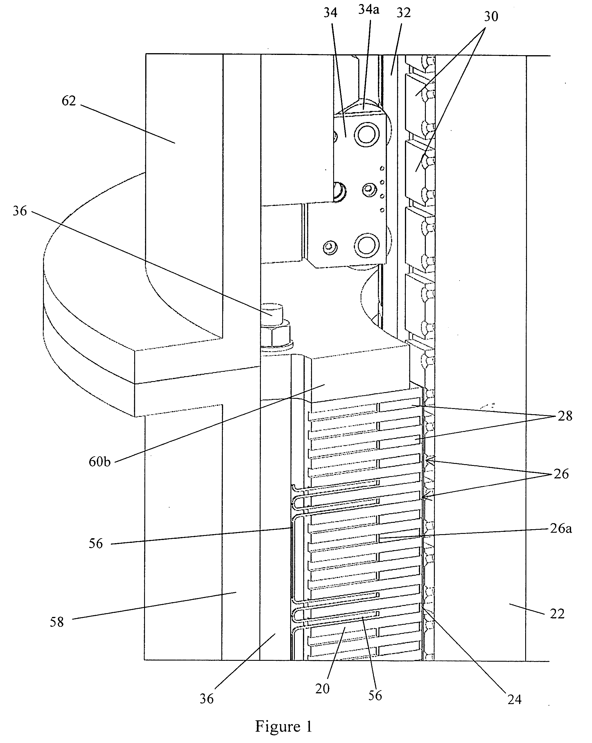
[0051] With reference to FIG. 1, a three-phase tubular electrical machine includes a stator 20 and a translator 22. The stator 20 has a cylindrical inner surface 24 that includes a series of annular slots 26 for receiving a series of coils 28 that together form a stator winding.

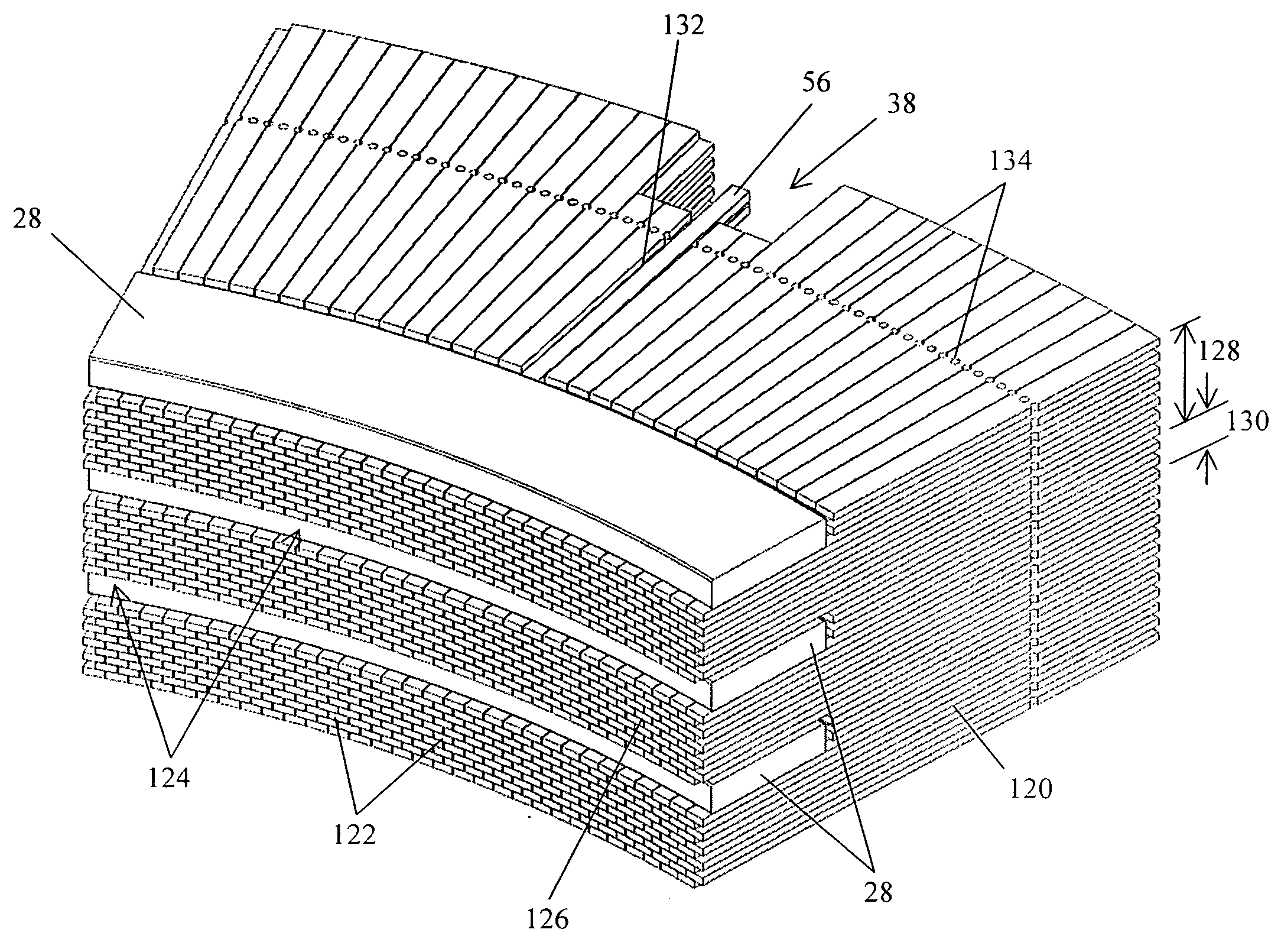
[0052] The translator 22 is formed in a number of individual sections that are mechanically attached together. The cylindrical outer surface of the translator 22 is covered by rows of permanent magnets 30. As shown most clearly in FIG. 6, the permanent magnets are arranged in such a way that the magnets in each row are skewed or shifted slightly with respect to each other in the axial direction. The offset between neighboring magnets reduces cogging forces. The magnets in each pair of axially adjacent rows have opposite polarity. For example, a row of magnets 30a might be N-pole and the axially adjacent rows of magnets 30b and 30c might be S-pole. Four steel strips 32 are provided on the outer surface of the...


PUM

PropertyMeasurementUnit
axial heightaaaaaaaaaa
thickaaaaaaaaaa
axial heightaaaaaaaaaa

Abstract

A stator for a tubular electrical generator or motor has a substantially cylindrical inner surface containing a series of axially-spaced slots for receiving the coils of a stator winding. The stator is formed from a plurality of stacked annular laminations that define the slots and the inner surface. The laminations comprise circumferentially-spaced radial slits defining fingers that extend radially outwards from their radially inner edges. The slits and fingers reduce the overall eddy losses in the stator while permitting simple manufacture, simple assembly and high radial thermal conduction for good cooling. In an alternative embodiment, the laminations and their fingers may be replaced by layers of batons of similar radial extent to the laminations.

Description

BACKGROUND OF THE INVENTION [0001] 1. Field Of The Invention [0002] The present invention relates to tubular electrical machines, and in particular to physically large tubular electrical motors and generators that are suitable for use as direct drive generators for converting wave energy into electrical power. [0003] 2. Description Of The Related Art [0004] It is known to use linear electrical machines as generators to convert the reciprocating movement captured by a wave energy machine into electrical power. [0005] Tubular electrical machines are similar to linear electrical machines but instead of having a flat stator they have a tubular stator where the slots for receiving the coils of the stator winding are formed in the cylindrical inner surface. The flat translator is replaced with a hollow or solid tubular translator with rows of permanent magnets mounted around its cylindrical outer surface. [0006] Tubular electrical machines offer considerable benefits over linear electrica...

Claims


Application Information

Patent Timeline
Patent Type & Authority Applications(United States)
IPC IPC(8): H02K41/00H02K1/00H02K15/00F03B13/16H02K1/12H02K1/14H02K1/16H02K41/03
CPCF03B13/16F05B2220/7066F05B2220/7068H02K1/12Y10T29/49009H02K2207/03Y02E10/38H02K1/16H02K7/1876H02K41/031Y02E10/30H02K1/165H02K15/024H02K35/02H02K1/185
Inventor LEFLEM, GRAHAM
Owner GE POWER CONVERSION
Why Eureka
Try Eureka