Magnetic core member for antenna module, antenna module and portable information terminal equipped with antenna module

a technology of magnetic core and antenna module, which is applied in the direction of ferromagnetic core loop antennas, inductance with magnetic cores, and particular array feeding systems, etc., can solve the problem of shortened distance, achieve high permeability, improve the communication distance of antenna modules, and increase the permeability of the whole magnetic core member

Inactive Publication Date: 2007-03-29
SONY CORP
View PDF8 Cites 57 Cited by
  • Summary
  • Abstract
  • Description
  • Claims
  • Application Information

AI Technical Summary

Benefits of technology

[0010] High permeability magnetic powders have been used conventionally as a magnetic core member in order to improve a communication distance of an antenna module. If magnetic powders are mixed with binder and shaped in a sheet member or plate member to use the member as a magnetic core member, a permeability of the whole magnetic core member can be increased by making large the particle size of magnetic powders.
[0012] In order to reduce the eddy current loss while a permeability of a magnetic core member is maintained high, most of conventional approaches are to limit a large particle size of magnetic powders and reduce an absolute quantity of magnetic powders to be mixed.
[0013] However, to reduce the absolute quantity of magnetic powders results in a thick and large magnetic core member, and in a thick antenna module. For example, a sheet thickness of a conventional magnetic core member having the structure described above is at least over 1 mm in order to obtain a communication distance of 100 mm of the magnetic core itself. The module thickness increases further by laminating a board for supporting the antennal coil and a shield plate for eliminating the influence of a metal portion inside the housing.
[0014] Recently, a portable information terminal is much more reqired compact and thin, and there is no room left in the housing of the portable information terminal for accommodating an antenna module of a large or thick size. As described above, an antenna module built in a compact electronic apparatus such as a portable information terminal is required to satisfy two contradictory requests for further improving a communication distance and further thinning a module thickness.
[0016] In order to solve the above issue, the present inventors have vigorously studied and found that an eddy current in a magnetic core member is generated on the surface facing an antenna coil stacked, and concentrated on an area facing a loop portion of the antenna coil. It has been found that by forming a recess portion in this area, a generation amount of eddy currents can be reduced.
[0018] By forming the recess portion, a gap corresponding to a depth of the recess portion is formed between the surface of the magnetic core member and the loop portion of the antenna coil, and intervention of this gap reduces the amount of eddy currents to be generated on the surface of the magnetic core member. The deeper the recess portion is, the generation of eddy current can therefore be expected to be suppressed. However, since the magnetic core member is positioned away from the loop portion of the antenna coil, the inductance of the antenna coil reduces and the communication distance is degraded. To avoid this, according to the present invention, an area where the recess portion is formed is set to at least the area facing the loop portion of the antenna coil to balance between reduction of the amount of the eddy current generation and prevention of the inductance from being lowered.

Problems solved by technology

However, as the particle size of magnetic powders is made large, a power loss caused by an eddy current loss of the magnetic core member becomes conspicuous, with an IC read voltage lowered and a communication distance shortened.

Method used


Image

  • Magnetic core member for antenna module, antenna module and portable information terminal equipped with antenna module
  • Magnetic core member for antenna module, antenna module and portable information terminal equipped with antenna module
  • Magnetic core member for antenna module, antenna module and portable information terminal equipped with antenna module

Examples


Embodiment Construction

[0032] An embodiment of the present invention will be described in the following by referring to the drawings.

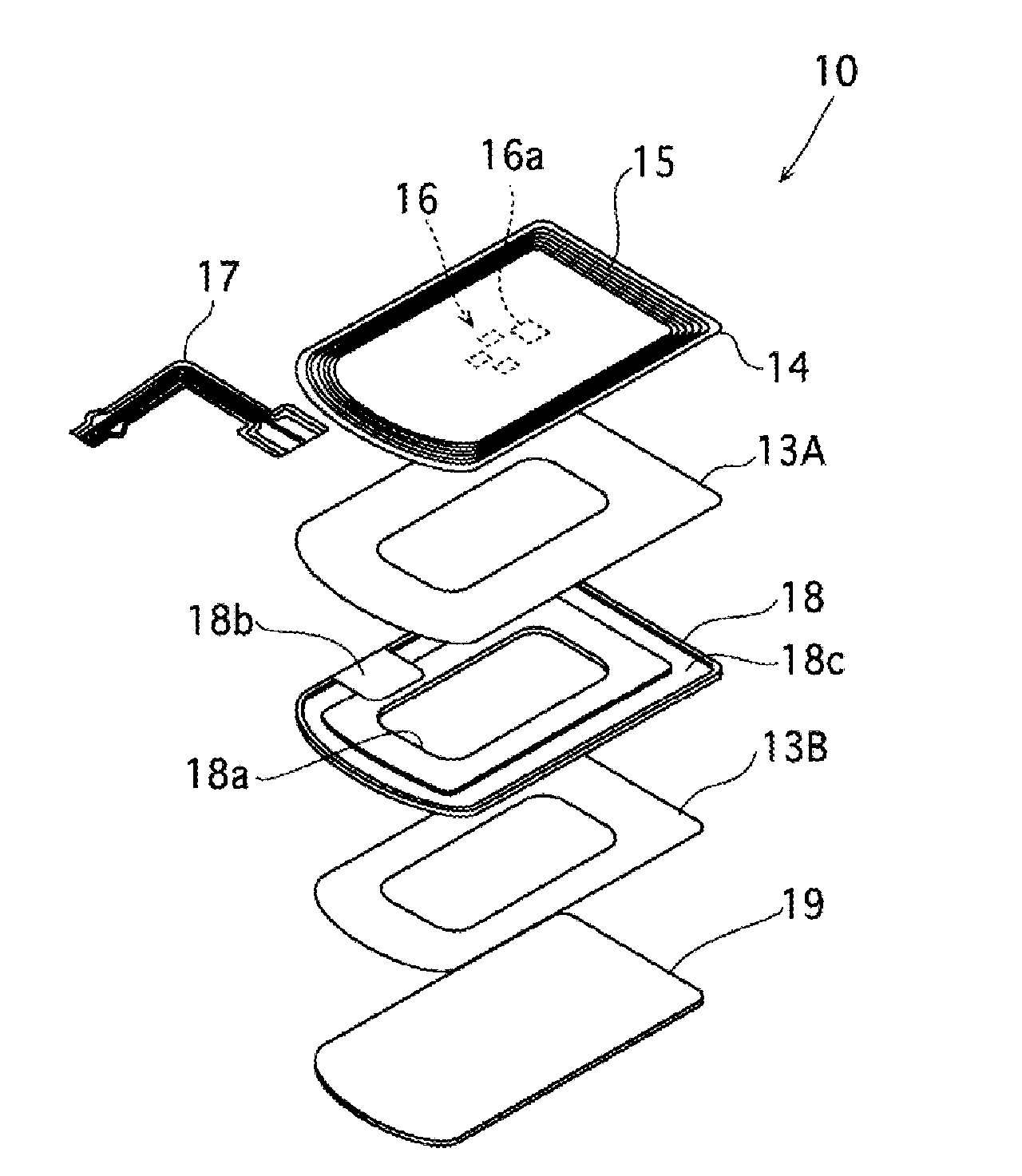
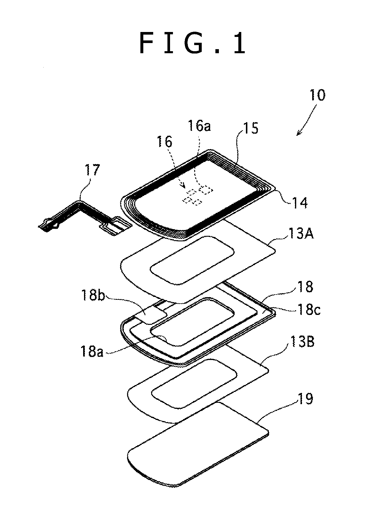
[0033]FIG. 1 and FIG. 2 are a broken perspective view and a cross sectional side view showing the structure of an antenna module 10 for non-contact data communications according to an embodiment of the present invention.

[0034] The antenna module 10 has a lamination structure of a baseboard 14 as a support body, a magnetic core member 18 and a metal shield plate 19. The baseboard 14 and magnetic core member 18 are stacked via an adhesive double coated sheet 13A, and the magnetic core member 18 and metal shield plate 19 are stacked via an adhesive double coated sheet 13B. In FIG. 2, the double-sided adhesive sheets 13A and 13B are not shown in the drawing.

[0035] Although the baseboard 14 is configured as an insulating flexible board made of a plastic film such as polyimide, polyethylene terephthalate (PET) and polyethylene naphthalate (PEN), it may be structured as a rigid ...


PUM


Abstract

There are provided a magnetic core member for an antenna module capable of improving a communication distance without thickening the module, an antenna module, and a portable information terminal equipped with the antenna module. A magnetic core member 18 for an antenna module 10 of the present invention has a ring groove 18c as a recess portion formed on the surface on the side stacking an antenna coil 15 in an area facing a loop portion of the antenna coil 15. An eddy current generated in the magnetic core member 18 in a high frequency magnetic field is concentrated on the surface of the magnetic core member 18 on the side stacking the antenna coil 15 in the area facing the loop portion of the antenna coil 15. According to the present invention, a ring groove 18c is provided in the area to reduce an amount of eddy currents to be generated and improve the communication distance characteristics of the antenna module.

Description

TECHNICAL FIELD [0001] The present invention relates to a magnetic core member for an antenna module suitable for use with a non-contact IC tag utilizing radio frequency identification (RFID) techniques, an antenna module and a portable information terminal equipped with the antenna module. BACKGROUND ART [0002] Conventionally, a device having an IC chip with recorded information and a resonance capacitor electrically connected to an antenna coil is known as a non-contact IC card and an identification tag utilizing RFID techniques (hereinafter, these are collectively called a “non-contact IC tag”). [0003] A non-contact IC tag is activated upon transmission of radio waves having a predetermined frequency (e.g., 13.56 MHz) from a transmission / reception antenna of a reader / writer, with an antenna coil of the non-contact IC tag. And, individual identification or authentication management becomes possible upon reading information recorded in an IC chip in response to a read command throu...

Claims


Application Information

Patent Timeline
Patent Type & Authority Applications(United States)
IPC IPC(8): H01Q1/24
CPCH01F5/003H01F17/04H01F2027/348H01Q21/0025H01Q7/06H01Q7/08H01Q1/243H01Q1/24H01Q7/00
Inventor AKIHO, HIRAKURYOSON, HIROYUKIGOTO, KAZUO
Owner SONY CORP
Why Eureka
Try Eureka