

Image display apparatus and light source unit
a technology of light source unit and display apparatus, which is applied in the direction of lighting and heating apparatus, television systems, instruments, etc., can solve the problems of increasing cost and large overall size of the apparatus, and achieve the effect of reducing cos
- Summary
- Abstract
- Description
- Claims
- Application Information
AI Technical Summary
Benefits of technology
Problems solved by technology
Method used
Image

Examples
first embodiment
[0050] First, a first embodiment of the invention will be described with reference to FIGS. 1 and 2.
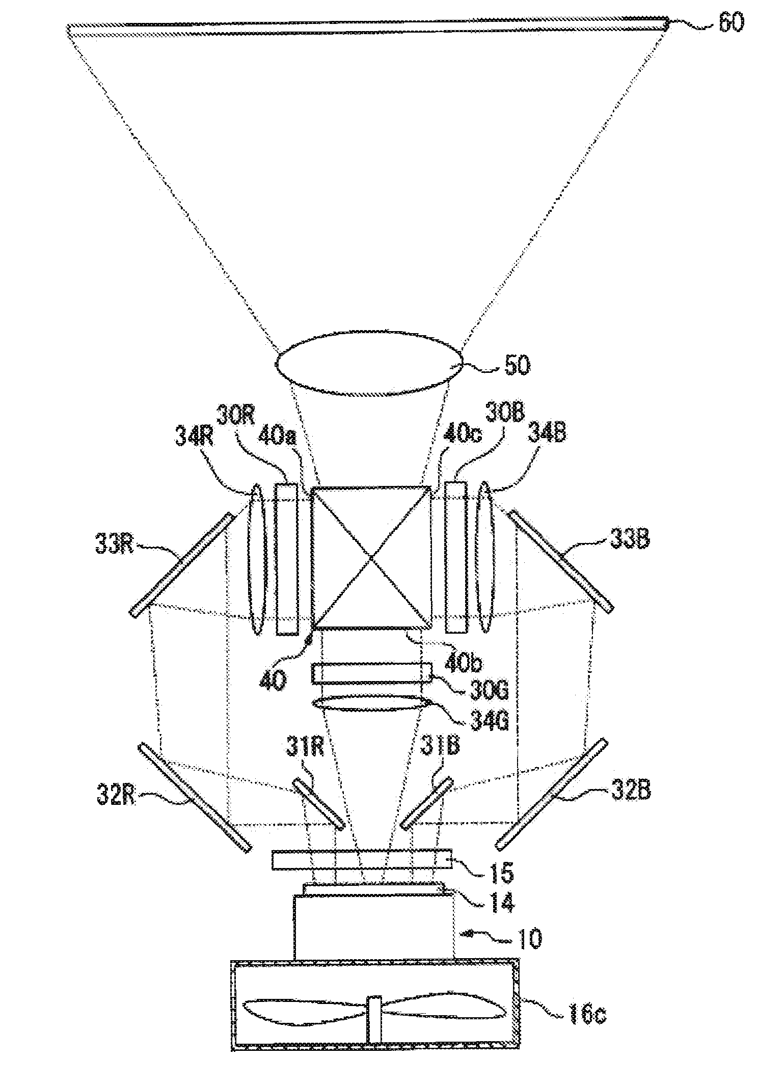
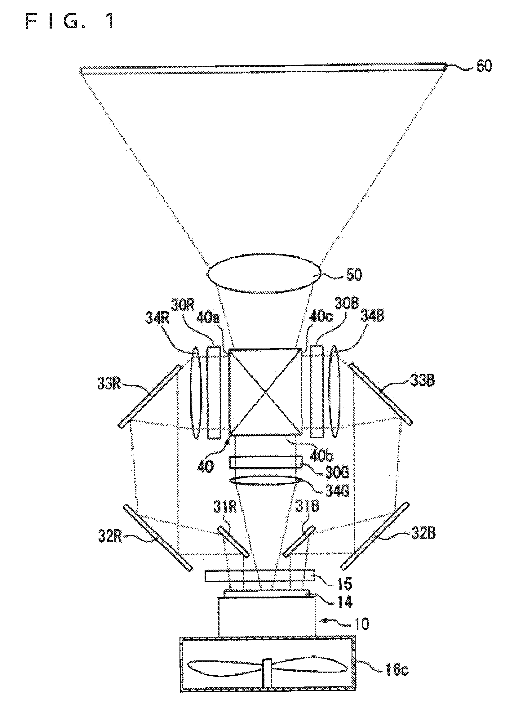
[0051] Referring to FIG. 1, an image display apparatus according to the first embodiment of the invention is exemplified as a projector 1 which projects a light beam onto a screen 60 in response to an image signal.
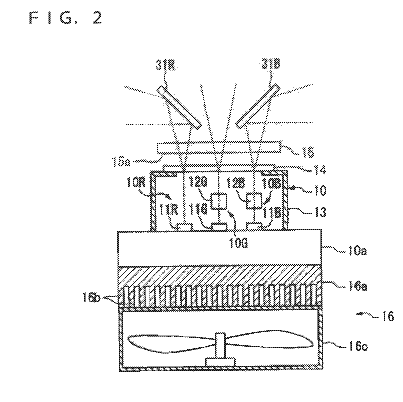
[0052] As shown in FIGS. 1 and 2, the projector 1 includes: a light source unit 10 having a red light source unit 10R which emits a red light beam (hereinafter referred to as an R light beam), a green light source unit 10G which emits a green light beam (hereinafter referred to as a G light beam), and a blue light source unit 10B which emits a blue light beam (hereinafter referred to as a B light beam); a plurality of transmitting liquid crystal light valves (light modulators: liquid crystal panels, hereinafter referred to as liquid crystal light valves) 30R, 30G, and 30B which modulate brightness of the R light beam, the G light beam, and the B light beam which are emitte...
second embodiment
[0069] Now, a second embodiment of the invention will be described in detail with reference to FIG. 3. Hereinafter, In the following embodiments of the invention, projectors having the same structure as the project 1 according to the first embodiment of the invention will be denoted as the same reference numeral, and descriptions thereof will be omitted.
[0070] A projector 70 of the second embodiment of the invention is different from that of the first embodiment in that an infrared cut filter 71 is included in the second embodiment of the invention.
[0071] Referring to FIG. 3, the infrared cut filter 71 is fastened to close the aperture 13a of the case body 13. The illumination equalizing element 14 is fastened to a surface of the infrared cut filter 71, which is opposite to the side where the laser beam sources 11R, 11G, and 11B are disposed. The infrared cut filter 71 transmits a visible light beam (approximately 380-780 nm) and cuts an infrared light beam (approximately over 780...
third embodiment
[0076] Now, a third embodiment of the invention will be described with reference to FIGS. 4A and 4B.
[0077]FIG. 4A is a plan view of a projector 80 according to the third embodiment of the invention. FIG. 4B is a side view of the projector 80 according to the third embodiment of the invention.
[0078] The projector 80 of the third embodiment of the invention is different from that of the first embodiment of the invention in that an optical path between the illumination equalizing element 14 and the liquid crystal light valves 30R, 30G, and 30B are uniform.
[0079] Referring to FIGS. 4A and 4B, in the projector 80, optical paths of the R light beam and the B light beam are curved within a horizontal surface, and an optical path of the G light beam is curved within a vertical surface. Specifically, the projector 80 includes: a first mirror 81 which converts an optical path of a light beam emitted from the laser beam source 11G by 90°; a second mirror 82 which reflects a light beam refle...
PUM
 Abstract
Description
Claims
Application Information