Diversity receiver
a receiver and diversity technology, applied in the field of receivers, can solve the problems and achieve the effects of low computing complexity, poor signal quality after diversity combining, and relatively inaccurate estimated channel information
- Summary
- Abstract
- Description
- Claims
- Application Information
AI Technical Summary
Benefits of technology
Problems solved by technology
Method used
Image
Examples
first embodiment
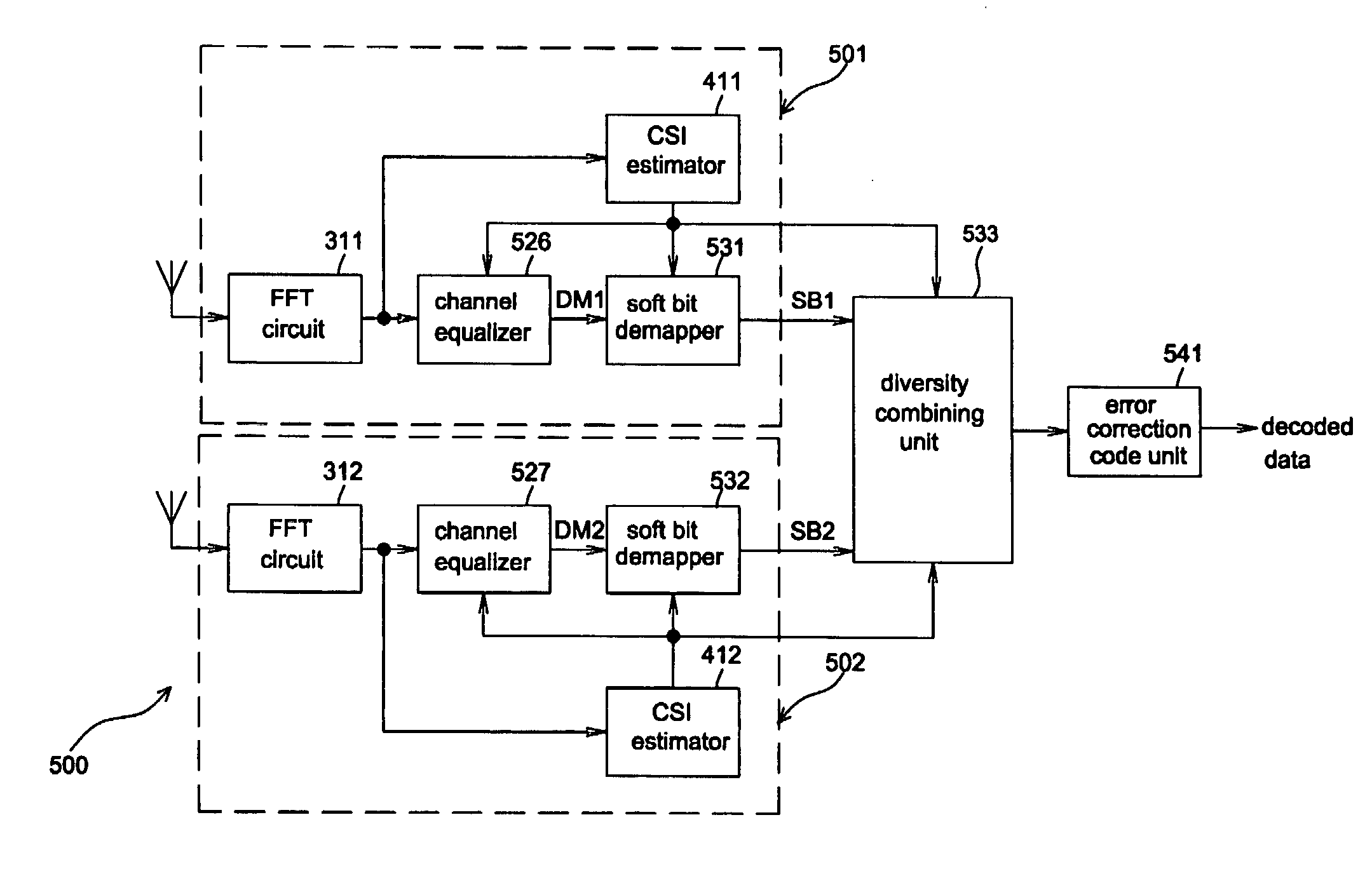
[0038] Referring to FIG. 5A, a diversity receiver 500 has two identical branches 501, 502 for receiving a first version of an input signal and a second version of an input signal. It comprises two FFT circuits 311, 312, two channel equalizers 526, 527, two channel state information estimators 411, 412, two soft bit demappers 531, 532, a diversity combining unit 533 and an error correction code unit 541. Since both of these two branches are identical for receiving and processing different versions of the input signal, only the branch 501 will be described below. Suppose that the FFT circuit 311 receives the first version of the input signal and generates a frequency-domain signal after performing Fourier transformation. The channel state information estimators 411 fetches the frequency-domain signal and extracts the contained reference signals (e.g. pilot signal) from the frequency-domain signal to produce a set of channel frequency response estimates H1 and the channel parameter CS...
second embodiment
[0043]FIG. 5C is an equivalent circuit of a diversity receiver according to the invention. Referring to FIG. 5A and FIG. 5C, channel equalizers 526, 527 are respectively equivalent to multipliers 561, 562 while the diversity combining unit 533 is equivalent to combination of multipliers 551, 552 and an adder 553. It should be noted that the adder 553 and a multiplexer 554 are merged into an adding and multiplexing unit 555 for simplicity. Regarding the branch 501 shown in FIG. 5C, firstly, the frequency-domain signal outputted from the FFT circuit 311 is multiplied by a reciprocal H1−1 of the channel frequency response estimate (or divided by the channel frequency response estimate H1) so that the first demodulated signal DM1 is generated. While receiving the first demodulated signal DM1, the soft bit demapper 531 need not modify the decision boundary, but directly performs symbol demapping to generate the first soft bit signal SB1. After the first soft bit signal SB1 and the second...
third embodiment
[0045]FIG. 5D is an equivalent circuit of a diversity receiver according to the invention. Since the front circuits to generate the first and the second demodulated signals DM1, DM1 are the same for both architectures shown in FIG. 5C and FIG. 5D, the description is omitted here. Referring to FIG. 5D, as for the branch 501, the multiplier 551 multiplies the first demodulated signal DM1 by the signal-to-noise ratio estimate SNR1. The soft bit demapper 531 modifies the decision boundary with the signal-to-noise ratio estimate SNR1, and performs symbol demapping to generate the first soft bit signal SB1. After the first soft bit signal SB1 and the second soft bit signal SB2 enter the diversity combining unit 533, bit-level signal combining or selecting operations are performed to generate the pre-correction signal.
PUM
 Abstract
Description
Claims
Application Information
 - R&D
- Intellectual Property
- Life Sciences
- Materials
- Tech Scout
- Unparalleled Data Quality
- Higher Quality Content
- 60% Fewer Hallucinations
Browse by: Latest US Patents, China's latest patents, Technical Efficacy Thesaurus, Application Domain, Technology Topic, Popular Technical Reports.
© 2025 PatSnap. All rights reserved.Legal|Privacy policy|Modern Slavery Act Transparency Statement|Sitemap|About US| Contact US: help@patsnap.com


