Digital Subscriber Line Diagnostic System

a technology of subscriber line and diagnostic system, applied in the field of telecommunication, can solve the problem that the endpoint customer has practically no means of knowing why the modem is not working, and achieve the effect of improving the performance of the dsl communication system

Inactive Publication Date: 2007-03-29
CALLAHAN CELLULAR L L C +1
View PDF37 Cites 13 Cited by
  • Summary
  • Abstract
  • Description
  • Claims
  • Application Information

AI Technical Summary

Benefits of technology

[0006] In one embodiment of the invention, a communication device transmits very low frequency signals in order to help diagnose the cause of a communication problem in a DSL communication system. In another embodiment of the invention, a communication device transmits very low frequency signals in order to help improve the performance of a DSL communication system. In yet another embodiment of the invention, very low frequency signals are used to help with the installation and / or configuration of a DSL modem.

Problems solved by technology

If a train-up is unsuccessful, the endpoint customer has practically no means of knowing why the modem is not working.
Sending a technician to a customer's premises is often referred to as a “truck roll.” Communications service providers strive to reduce the number of truck rolls because there are significant costs associated with them.
These costs may involve, for example, maintaining trucks, technicians, handheld test equipment, etc.
Furthermore, truck rolls can be time consuming and may therefore be inconvenient for customers who will experience an interruption in DSL services while the cause of the problem is being diagnosed.

Method used


Image

  • Digital Subscriber Line Diagnostic System
  • Digital Subscriber Line Diagnostic System
  • Digital Subscriber Line Diagnostic System

Examples


Embodiment Construction

[0020] While the invention is susceptible to various modifications and alternative forms, a specific embodiment thereof is shown by way of example in the drawings and will herein be described in detail. It should be understood, however, that there is no intent to limit the invention to the particular form disclosed, but on the contrary, the invention is to cover all modifications, equivalents, and alternatives falling within the spirit and scope of the invention as defined by the claims.

I. System Overview

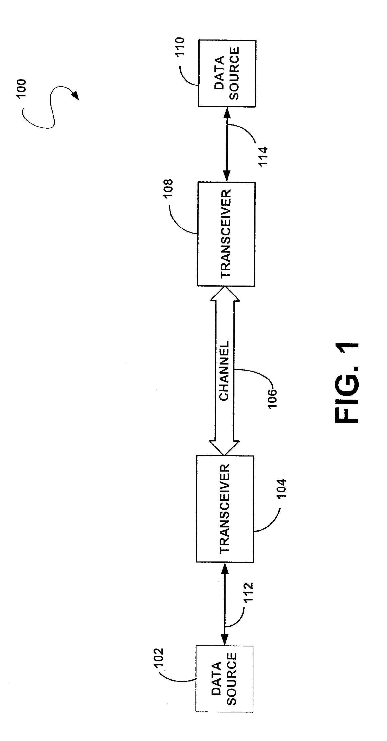
[0021]FIG. 1 is a block diagram illustrating one possible configuration of a communication system 100 in which the present invention may be implemented. Communication system 100 includes a data source 102, a transceiver 104, a communication channel 106, a transceiver 108, and a data source 110. Data source 102 is coupled to transceiver 104 via connection 112, and data source 110 is coupled to transceiver 108 via connection 114. Transceivers 104 and 108 are coupled together via ch...


PUM


Abstract

A communication device transmits very low frequency signals in order to help diagnose the cause of a communication problem in a DSL communication system. The communication problem may be, for example, the inability of a remote data transceiver unit (DTU-R) to successfully train-up with a central data transceiver unit (DTU-C). The very low frequency signals may be used to communicate the status or settings of the remote transceiver unit to the DTU-C, to download settings parameters or executable code to the DTU-R, or to coordinate the transmission of testing signals.

Description

CROSS REFERENCE TO RELATED APPLICATION [0001] This application is a continuation of U.S. patent application Ser. No. 10 / 409,260, filed Apr. 8, 2003, which is a continuation of U.S. Pat. No. 6,574,308, issued Jun. 3, 2003, all of which are herein incorporated by reference.FIELD OF THE INVENTION [0002] The present invention relates generally to the field of telecommunication, and more particularly to digital subscriber line (DSL) communication systems. BACKGROUND OF THE INVENTION [0003] With the explosion in the growth of Internet usage among both businesses and households, telephone companies have been pressured to provide affordable, high bandwidth access that will support high-speed multimedia services, such as video on demand, high speed Internet access, and video conferencing. To meet this demand, telephone companies are increasingly turning to xDSL technology. The xDSL technology, while having several different embodiments, can provide throughput rates over 100 times faster than...

Claims


Application Information

Patent Timeline
Patent Type & Authority Applications(United States)
IPC IPC(8): H04M1/24H04M3/08H04M3/22
CPCH04M3/304
Inventor MACDONALD, ALISTAIR MALCOLMCHAPMAN, JOSEPH Q.
Owner CALLAHAN CELLULAR L L C
Why Eureka
Try Eureka