Microresonator optical switch

a micro-resonator and optical switch technology, applied in the field of optical modulators and switches, can solve the problems of extremely fast response time, notoriously weak, and few physical mechanisms available to modulate the refractive index of silica fibers

Active Publication Date: 2007-03-29
THE BOARD OF TRUSTEES OF THE LELAND STANFORD JUNIOR UNIV
View PDF13 Cites 22 Cited by
  • Summary
  • Abstract
  • Description
  • Claims
  • Application Information

AI Technical Summary

Benefits of technology

[0012] In certain embodiments, a method of optical switching comprises providing an optical switch comprising an optical coupler and a microresonator optically coupled to the optical coupler and having a plurality of nanoparticles. The method further comprises receiving an optical pulse by the optical switch. At least a portion of the optical pulse is absorbed by the nanoparticles of the microresonator such that at least a portion of the optical switch undergoes an increase of the number of free carriers therein and a corresponding refractive index change when the optical pulse has an optical power greater than a predetermined threshold level.

Problems solved by technology

Unfortunately, very few physical mechanisms are available to modulate the refractive index of a silica fiber in order to induce switching.
The widely-studied Kerr effect has an extremely fast response time (e.g., a few femtoseconds) but it is notoriously weak.

Method used


Image

  • Microresonator optical switch
  • Microresonator optical switch
  • Microresonator optical switch

Examples


Embodiment Construction

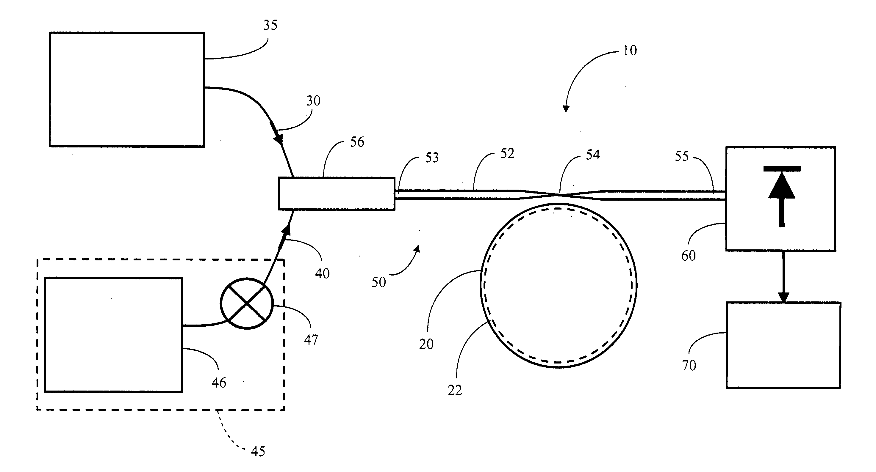
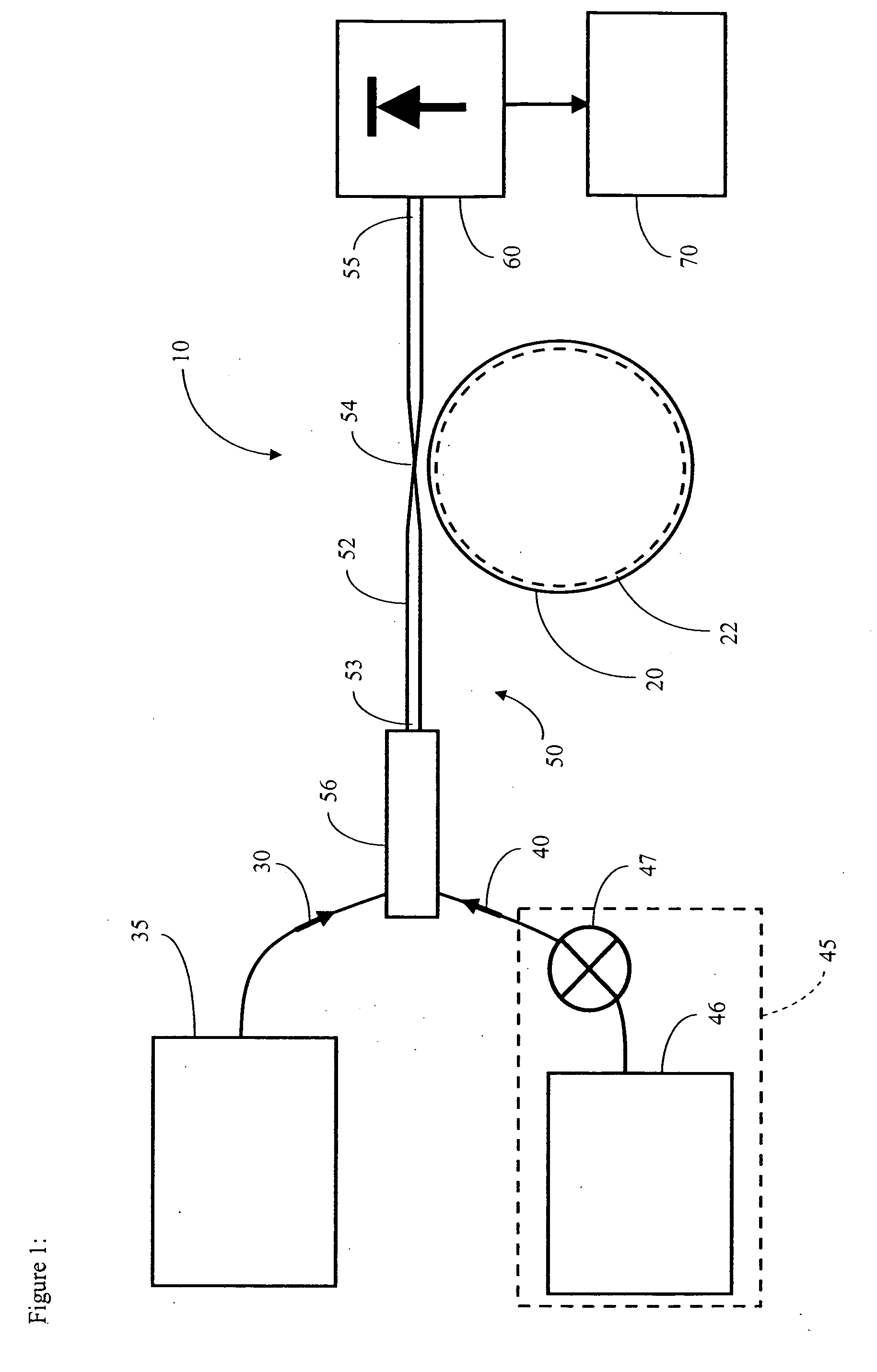
[0032]FIG. 1 schematically illustrates an optical switch 10 in accordance with certain embodiments described herein. The optical switch 10 comprises a microresonator 20 comprising a plurality of nanoparticles. The microresonator 20 is configured to receive signal light 30 having a signal wavelength and to receive a pump pulse 40 having a pump wavelength. At least a portion of the microresonator 20 is responsive to the pump pulse 40 by undergoing a refractive index change at the signal wavelength.

[0033] As schematically illustrated by FIG. 1, in certain embodiments, the optical switch 10 further comprises an optical coupler 50 optically coupled to the microresonator 20 and configured to be optically coupled to a signal source 35 and to a pump source 45. The optical coupler 50 transmits the pump pulse 40 from the pump source 45 to the microresonator 20 and transmits the signal light 30 from the signal source 35 to the microresonator 20.

[0034] In certain embodiments, the microresonat...


PUM

PropertyMeasurementUnit
diameteraaaaaaaaaa
poweraaaaaaaaaa
diameteraaaaaaaaaa

Abstract

An optical switch includes a microresonator comprising a plurality of nanoparticles. The microresonator is configured to receive signal light having a signal wavelength and to receive a pump pulse having a pump wavelength. At least a portion of the microresonator is responsive to the pump pulse by undergoing a refractive index change at the signal wavelength.

Description

CLAIM OF PRIORITY [0001] This application claims the benefit of priority to U.S. Provisional Patent Application No. 60 / 717,637, filed Sep. 16, 2005, which is incorporated in its entirety by reference herein.BACKGROUND OF THE INVENTION [0002] 1. Field of the Invention [0003] The present application relates generally to optical modulators and switches. [0004] 2. Description of the Related Art [0005] All-optical fiber modulators and switches are important devices that have been researched for many years mainly because of the desire for low-loss, low-power, fiber-interfaced, optically-addressable switching devices in optical communication and fiber sensor systems. These systems include, but are not limited to, periodic self-healing communication networks, re-configurable optical signal processing, packet switching for local area networks, bit switching, towed sensor arrays, and testing of fiber links. [0006] Unfortunately, very few physical mechanisms are available to modulate the refra...

Claims


Application Information

Patent Timeline
Patent Type & Authority Applications(United States)
IPC IPC(8): G02B6/26G02B6/42
CPCB82Y20/00G02F2001/0113C03B19/1095C03C12/00C03C17/245C03C2217/213C03C2218/153C03C2218/32G02B6/12007G02B6/29341G02F1/0126G02F1/0147G02F2202/36G02F2203/055G02F1/0115C03B19/1055G02F1/0113
Inventor DIGONNET, MICHEL J.F.TEWARY, ANURANJITABRONGERSMA, MARK
Owner THE BOARD OF TRUSTEES OF THE LELAND STANFORD JUNIOR UNIV
Why Eureka
Try Eureka