Wavelength selective optical focusing device using optical fiber and optical module using the same

a wavelength selective and optical focusing technology, applied in the direction of optical waveguide light guide, instruments, optics, etc., can solve the problems of complex manufacturing process, low efficiency of structure in radiating optical signals to the outside of the core, and insufficient detection of optical signals having a high coupling factor, so as to prevent aging and excellent reproducibility in manufacturing

Inactive Publication Date: 2007-03-29
ELECTRONICS & TELECOMM RES INST
View PDF9 Cites 31 Cited by
  • Summary
  • Abstract
  • Description
  • Claims
  • Application Information

AI Technical Summary

Benefits of technology

[0007] The present invention provides a wavelength selective optical focusing device using an optical fiber, which has excellent reproducibility in manufacturing and prevents aging, and an optical module using the same.

Problems solved by technology

However, the above structure has a low efficiency in radiating an optical signal to the outside of the core 12, and can be used to monitor an optical signal but is not adequate to detect an optical signal having a high coupling factor.
The above planar waveguide is disadvantageous in that its manufacturing process is complicated and the mode matching with the optical fiber must be correctly achieved so as to minimize loss in transmitting the optical signal.
However, the above FBG 28 formed using ultraviolet rays (UV) is disadvantageous in that its reproducibility in manufacturing is reduced, aging effects, such as changes in refractive index, are severely generated, and it is difficult to have the maximum optical coupling efficiency above 50%.

Method used


Image

  • Wavelength selective optical focusing device using optical fiber and optical module using the same
  • Wavelength selective optical focusing device using optical fiber and optical module using the same
  • Wavelength selective optical focusing device using optical fiber and optical module using the same

Examples


Embodiment Construction

[0018] Now, preferred embodiments of the present invention will be described in detail with reference to the annexed drawings. In the drawings, the same or similar elements are denoted by the same reference numerals even though they are depicted in different drawings. In the following description of the present invention, a detailed description of known functions and configurations incorporated herein will be omitted when it may make the subject matter of the present invention rather unclear.

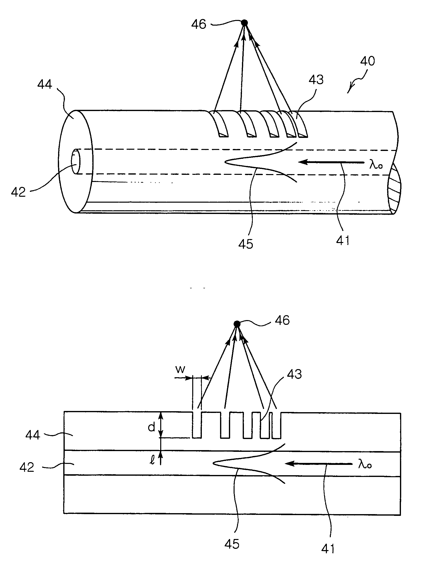
[0019]FIGS. 3A and 3B illustrate a wavelength selective optical focusing device using an optical fiber of the present invention.

[0020]FIG. 3A is a perspective view of the wavelength selective optical focusing device 40 using the optical fiber of the present invention, and FIG. 3B is a sectional view of the wavelength selective optical focusing device 40.

[0021] The wavelength selective optical focusing device 40 of the present invention comprises a core 42, along which an optical signal 41 is ...


PUM


Abstract

The present invention provides a wavelength selective optical focusing device using the cladding-etching of an optical fiber and an optical module using the same. The wavelength selective optical focusing device includes a core for transmitting an optical signal therethrough; and a cladding layer surrounding the core and having a plurality of grooves formed in the outer circumferential surface thereof such that the grooves are changed at a designated rate, wherein an optical signal having a designated wavelength guided by the core is focused to the outside of the cladding layer by the grooves.

Description

BACKGROUND OF THE INVENTION [0001] 1. Field of the Invention [0002] The present invention relates to an optical focusing device, and more particularly to a wavelength selective optical focusing device using the cladding-etching of an optical fiber and an optical module using the same. [0003] 2. Description of the Related Art [0004] In order to detect an optical signal traveling through a core of an optical fiber, a path of a core mode of the optical signal transmitted through the core must be changed. However, since the core of the optical fiber is generally coated with a cladding layer having a relative large thickness, the core mode is rarely affected by external factors. For this reason, in order to detect the optical signal from the optical fiber, the optical fiber must be physically deformed. The physical deformation of the optical fiber so that the optical signal is detected from the optical fiber is performed by various methods. One method, which is most easily performed usin...

Claims


Application Information

Patent Timeline
Patent Type & Authority Applications(United States)
IPC IPC(8): G02B6/34G02B6/30G02B6/42
CPCG02B6/02066G02B6/4203G02B6/02085
Inventor YOON, SHIN YOUNGLEE, SEI HYOUNGKANG, HYUN SEO
Owner ELECTRONICS & TELECOMM RES INST
Why Eureka
Try Eureka