Spreader insert for a retractor system

a retractor and insert technology, applied in the field of surgical instruments, can solve the problems of obstructing the view of the surgeon, reducing the surgical field, and and achieve the effect of reducing the “creep” of muscle or other tissue into the surgical field

Active Publication Date: 2007-03-29
HOLMED
View PDF12 Cites 53 Cited by
  • Summary
  • Abstract
  • Description
  • Claims
  • Application Information

AI Technical Summary

Benefits of technology

[0010] In use, the whole retractor assembly is introduced into the surgical field. Upon introduction, the initial configuration of the spreader insert is the closed position in that the downwardly extending blades of the spreader insert are tilted inwardly. Thus, the distal ends of each blade are almost touching one another to allow ease of introduction. Once inserted at the desired location, the base retractor forms a circular field of visibility. The surgeon then causes the blades to be expanded outwardly by operating the fasteners of the spreader insert of the first embodiment of the invention to rotate the blades outwardly, or by releasing the blades in the spring-out embodiment. In either case, the expanded blades act to spread the muscle and tissue further to provide retraction beyond the ring formed by the base retractor. The additional expansion of the opening provided by the base retractor is extended in the direction of head-to-toe of the patient, as opposed to spine to stomach. Thus, by using the insert with a ring-type retractor, the “creep’ of muscle or other tissue into the surgical field is reduces thus leaving a larger and more secure surgical area to be exposed for surgical access.

Problems solved by technology

However, such strong instruments are usually of a greater thickness and this may act to obstruct the view of the surgeon.
Additionally, another problem arises with respect to ring-type surgical retractors in that they retract the muscle and tissue in a circular region which does not always provide enough visibility in certain procedures.
However, this does not always provide enough visibility and can still result in muscle and tissue encroaching back into the surgical field during the surgical procedure.

Method used


Image

  • Spreader insert for a retractor system
  • Spreader insert for a retractor system
  • Spreader insert for a retractor system

Examples


Embodiment Construction

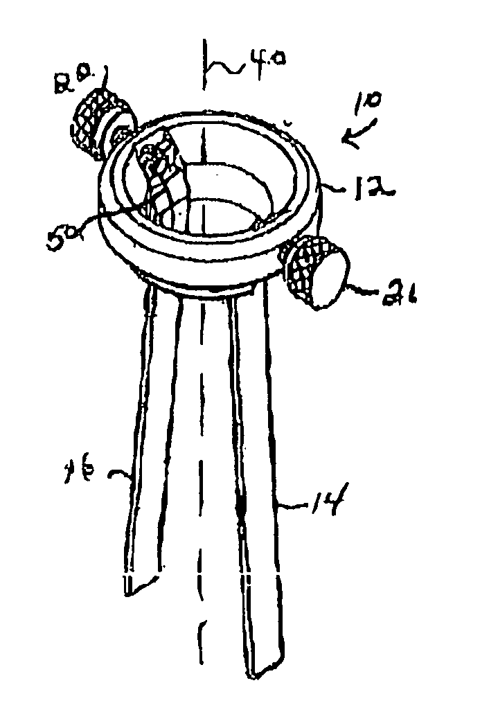
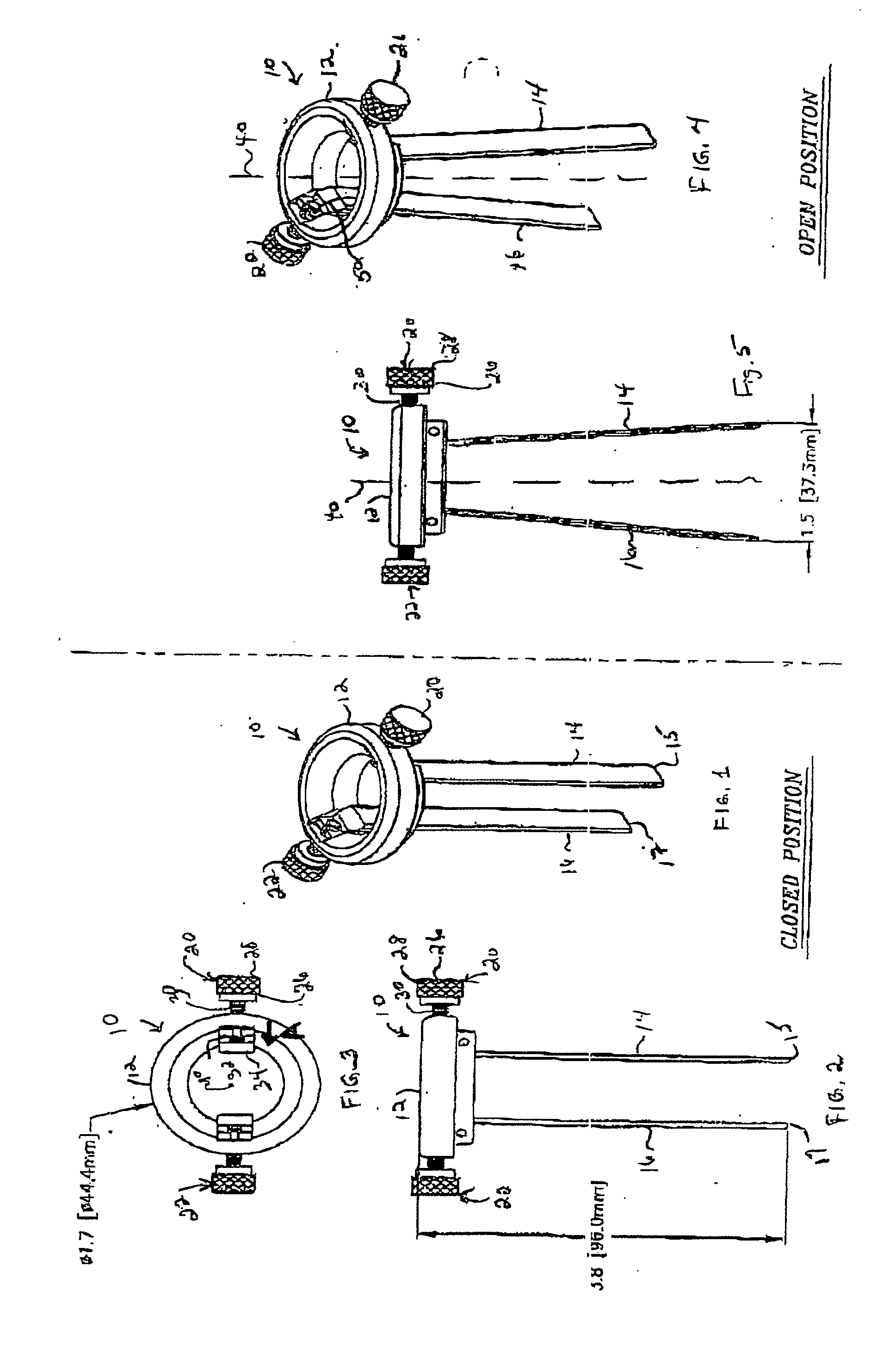
[0023]FIG. 1 is an isometric illustration of the spreader insert 10 of the present invention. The spreader insert 10 comprises a head portion 12 and a first blade 14 and a second blade 16. It is noted that the illustrative embodiment of FIG. 1 includes two blades, 14 and 16. However, it should be understood that the spreader insert 10 can be readily adapted to include more than two downwardly extending blades, such as those illustrated in FIG. 1, while remaining within the scope of the present invention. Blades 14 and 16 are coupled to the head 12 by means of fasteners 20 and 22. These are also visible in FIG. 2.

[0024]FIG. 3 is a top plan view of the insert 10 of the present invention illustrating the fasteners 20 and 22 in greater detail. More specifically, fastener 20 includes a screw 26 having a head 28 and a threaded shaft 30. An end 32 of the threaded shaft 30 is coupled to the tip 34 of the blade 14. When the screw head 28 is rotated in a first direction, the tip 34 is pushed...


PUM


Abstract

A spreader insert for use with a surgical retractor is provided. The spreader insert includes a circular head with two or more downwardly extending blades. One end of each blade of the insert is rotatably fastened to the head of the insert, such that each blade can be tilted inwardly or extended outwardly from a central axis of the device. Suitable fasteners are provided to rotate the blades from a closed position in which the distal ends of the blades are almost touching each other in order to improve ease of introduction into the surgical field. In an open position, the blades rotate outwardly to hold body tissue in place. Alternatively, the entire spreader insert is machined from a hardenable steel tube, the blades of which are formed so that, when released, they spring outwardly to an open position.

Description

CROSS-REFERENCE TO RELATED APPLICATION [0001] The present application claims the benefit of U.S. Provisional Patent Application Ser. No. 60 / 721,426, which was filed on Sep. 28, 2005, by Russell P. Holmes for a SPREADER INSET FOR A RETRACTOR SYSTEM, which is hereby incorporated by reference.BACKGROUND OF THE INVENTION [0002] 1. Field of the Invention [0003] This invention relates to surgical instrumentation, and more particularly, to instrumentation for use in spinal surgery and other types of surgical procedures. [0004] 2. Background Information [0005] Surgery on the spine is becoming more prevalent as better processes for performing many different types of spinal surgery are developed for procedures such as disk repair, vertebral fracture repair, correcting the effects of osteoporosis, bone grafts, tumor removal, scoliosis, and the like. [0006] Many different types of surgical instruments are used both to clear the field for the surgeon and to allow the spine surgeon access to the ...

Claims


Application Information

Patent Timeline
Patent Type & Authority Applications(United States)
IPC IPC(8): A61B1/32
CPCA61B17/02A61B2017/00862A61B17/0293A61B17/0206
Inventor HOLMES, RUSSELL P.
Owner HOLMED
Why Eureka
Try Eureka