Auto-assembling system for small shell devices

a technology of auto-assembling system and shell device, which is applied in the direction of electrical apparatus casing/cabinet/drawer, instruments, manufacturing tools, etc., can solve the problems of too high cost for media or small-sized enterprises to invest, and achieve the effects of reducing equipment cost, improving productivity and efficiency, and increasing the fram

Inactive Publication Date: 2007-04-05
CHUNG YUAN CHRISTIAN UNIVERSITY
View PDF4 Cites 14 Cited by
  • Summary
  • Abstract
  • Description
  • Claims
  • Application Information

AI Technical Summary

Benefits of technology

[0010] Another purpose of this invention is to provide one auto-assembling system to combine the control circuit to control the transportation and assemble the frames and covers to assemble the small shell devices; it can also collect the frames and covers composition more efficient.
[0011] One more purpose of this invention is to provide an auto-assembling system, it is not only to increase the frames and covers assembly yield rate, also can reduce the equipment cost and improve the productivity and efficient.

Problems solved by technology

Although the lens manufactures were been attention by market during the digital still camera was on the way, it was also out-performance when the mobile phone camera is going to replace the digital still camera lens.
Due to the mechanical arms need to reach to the 3D dimension accurate control, the whole control system includes the software and hardware equipment, plus the vacuum inhale equipment which cost is too expensive for the media or small size enterprise to invest.

Method used


Image

  • Auto-assembling system for small shell devices
  • Auto-assembling system for small shell devices
  • Auto-assembling system for small shell devices

Examples


Embodiment Construction

[0025] Some sample embodiments of the invention will now be described in greater detail. Nevertheless, it should be recognized that the present invention can be practiced in a wide range of other embodiments besides those explicitly described, and the scope of the present invention is expressly not limited expect as specified in the accompanying claims. Then, the components of the different elements are not shown to scale. Some dimensions of the related components are exaggerated and meaningless portions are not drawn to provide clearer description and comprehension of the present invention.

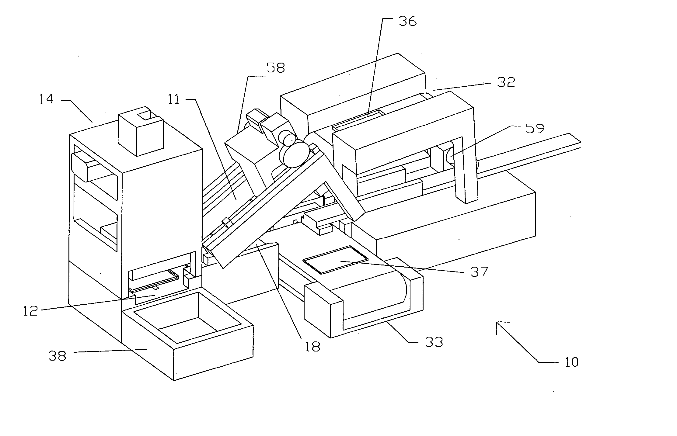
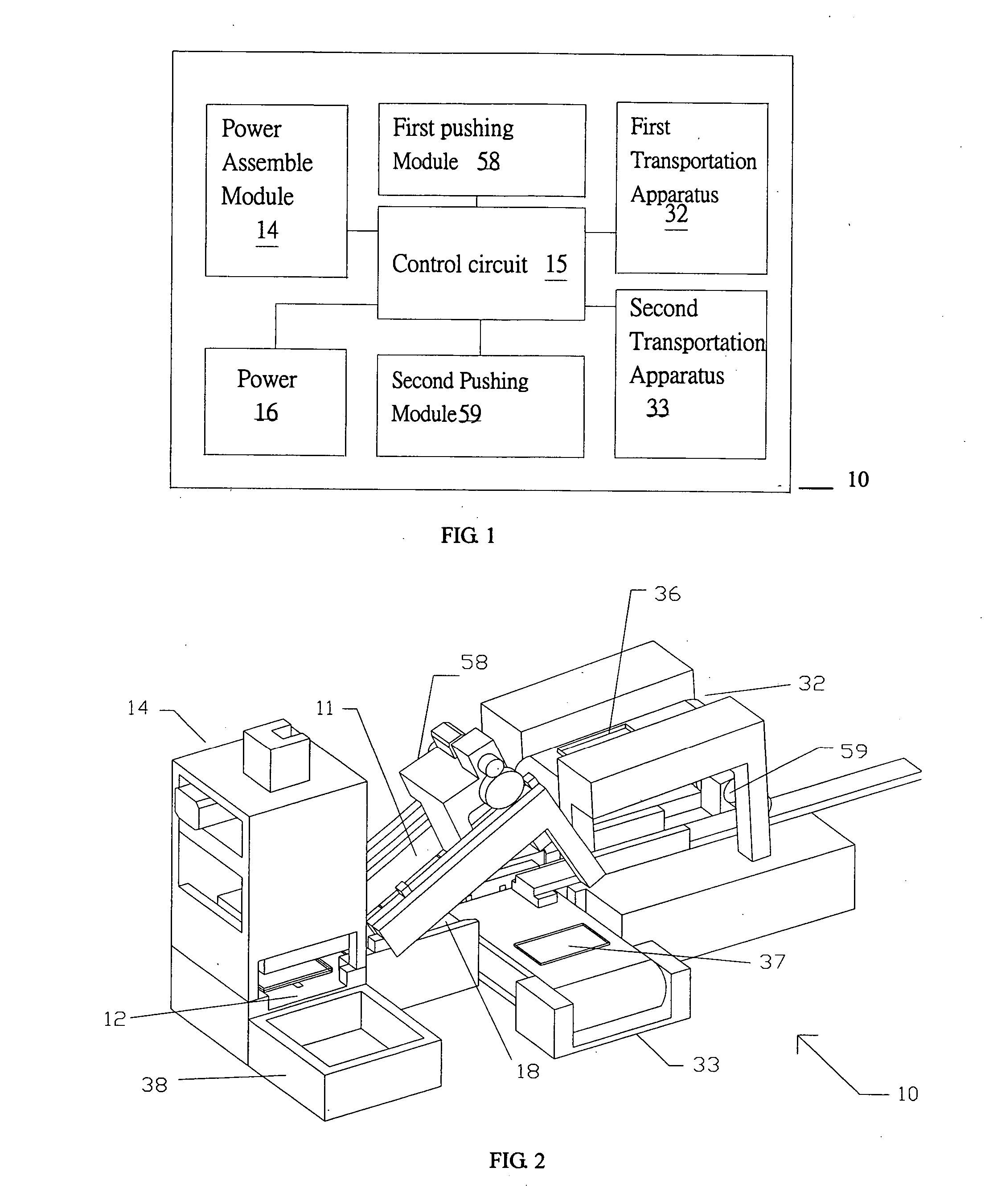
[0026] Referring now more particularly to the accompanying drawings, FIG. 1 shows a block diagram of the auto-assembling system for the small shell devices of the present invention. The auto-system 10 itself comprises the first transportation apparatus 32, the second transportation apparatus 33, the first driving module 58, the second driving module 59, the power assemble module 14, the control ...


PUM

PropertyMeasurementUnit
angleaaaaaaaaaa
tilting angleaaaaaaaaaa

Abstract

The present invention discloses an auto-assembling system for small shell devices. The system includes a first transportation component, a second transportation component, a first driving module, a second driving module, a power assembling module and a control circuit. The first transportation component having a first transportation belt and the second transportation component having a second transportation belt are used to transport the frames or the covers of the devices. The first driving module configured on the first transportation component is used to move the frames or the covers transported by the first transportation component to an assembling area downstream a slide. The second driving module configured on the second transportation component is used to move the frames or the covers transported by the second transportation component to the assembling area along a track. The power assembling module configured on the end of the first transportation component and the second transportation component is used for vertically pressing downwardly the frames and the covers such that the frames and the covers can be assembled. The control circuit connects to the first transportation component, the second transportation component, the first driving module, the second driving module and the power assembling module.

Description

FIELD OF THE INVENTION [0001] This invention relates to an auto-assembling system and, more particularly to an auto-assembling system for small and thin devices which uses to auto-assemble and collect the assembling frames and covers of the small shell devices. BACKGROUND OF THE INVENTIONDescription of the Prior Art [0002] Generally speaking, the mobile phone components can be divided into four categories: active devices, passive devices, mechanism, and functional devices. In view of the mobile phone, the active devices (briefly, which can perform the power-on / off function) have three main component vendors: (1) IC related, like Baseband IC or RF IC, audio and video IC; (2) Panel; (3) OLED. Passive devices include: resistors, capacitor (MLCC), inductor, antenna, filter, and oscillator. In Mechanism (performing the mechanical procedure is called mechanical devices) is not only provided smoothly but also have the cooperation opportunities with international companies. Regarding the fu...

Claims


Application Information

Patent Timeline
Patent Type & Authority Applications(United States)
IPC IPC(8): B23P21/00
CPCB23P19/001Y10T29/53078Y10T29/53378B23P21/00
Inventor WANG, SHIN MINGCHEN, TING KUO
Owner CHUNG YUAN CHRISTIAN UNIVERSITY
Why Eureka
Try Eureka