Tubular assembly and method

a technology of tubular assembly and tubular tubes, which is applied in the direction of separation process, filtration separation, dispersed particle separation, etc., can solve the problems of inability to accurately and repeatedly position and seal working devices within metal tubes or conduits, inability to achieve accurate and repeated positioning and sealing, and inability to achieve critical integrity of filter seal to the walls of conduits or passageways

Inactive Publication Date: 2007-04-05
SAVANNAH RIVER NUCLEAR SOLUTIONS
View PDF15 Cites 6 Cited by
  • Summary
  • Abstract
  • Description
  • Claims
  • Application Information

AI Technical Summary

Problems solved by technology

Positioning and sealing working devices within a metal tube or conduit is a difficult task and is quite time consuming when done accurately and repeatedly.
In many applications the integrity of the seal of the filter to the walls of a conduit or passageway is not critical as it is satisfactory for a relatively high percentage of particles to be removed.
Brazing or conventional welding does not work well due to loss of filter efficiency caused by the flow of molten metal around the perimeter of the filter in the gap between the filter and the tube inner wall.
This technique was unsuccessful because ovalization rather than concentric or circular reduction of the tube inside diameter resulted in a gap that creates a path for the hydride particles to pass to the supply side of the filter.
Additionally, pressurization of the tube resulted in expansion of the tube away from the filter.
This method also results in some loss of filter efficiency since gas flow through the perimeter surface area of the filter would be blocked by contact with the tubing.
For small parts similar to those used for a hydrogen reactor, shrink fitting was not practical since temperature differences between the two parts of approximately 700° F. degrees would have been required.

Method used


Image

  • Tubular assembly and method
  • Tubular assembly and method
  • Tubular assembly and method

Examples


Embodiment Construction

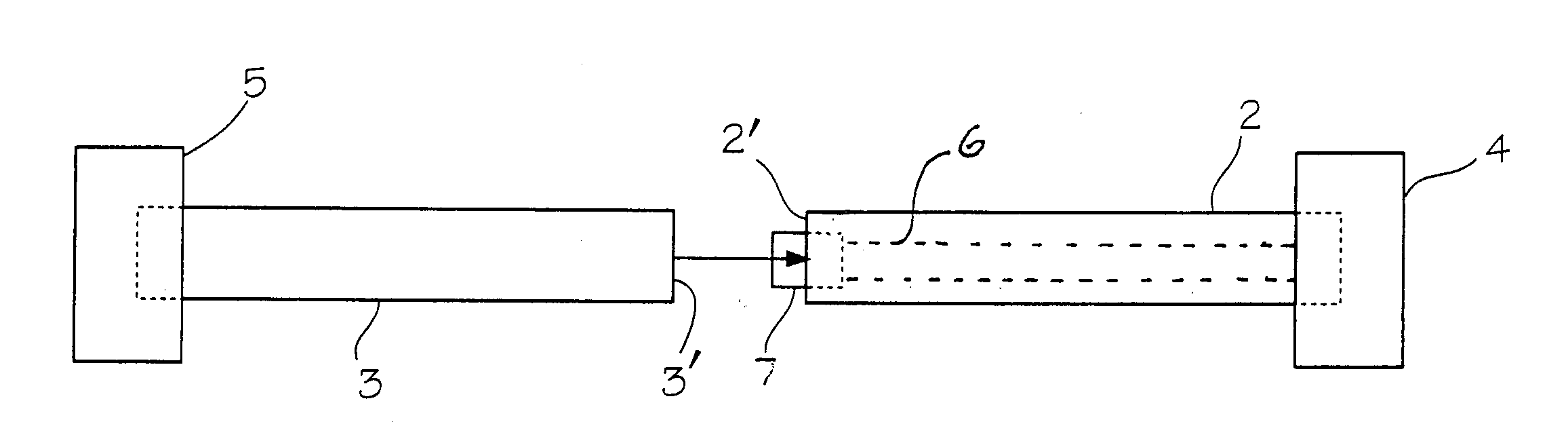
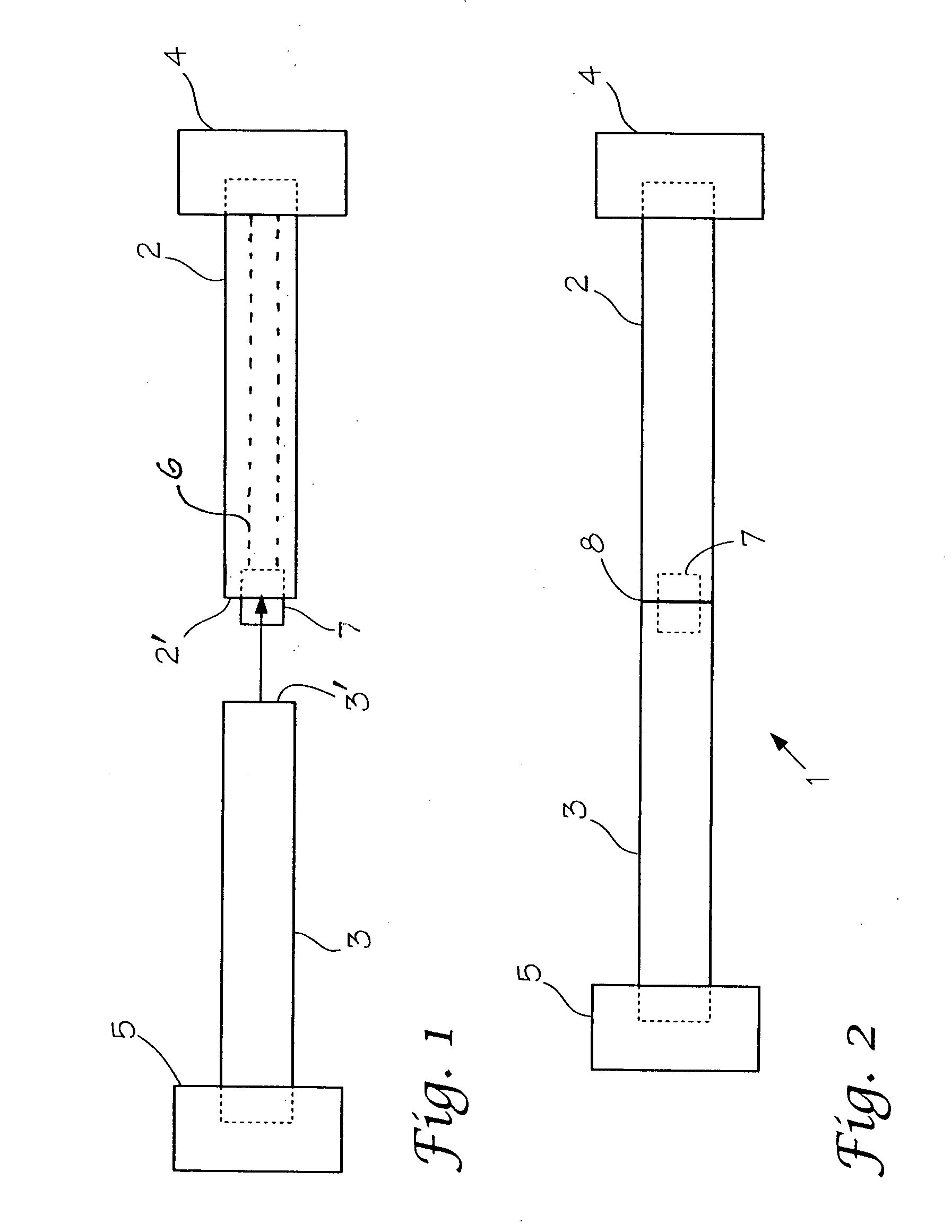
[0017] In the art, terms such as “friction welding”, “spin welding” and “inertial welding” can be found. These welding processes can generally be referred to as “solid state welding.” Usually frictional welding is carried out by moving one component relative to another on a common interface while applying a compressive force across the interface that forms the joint. The friction heat generated at the interface softens both components and when they become plasticized the interface material is extruded out of the edges of the joint so that clean material from each component is left along the original interface. The relative motion is then stopped and a higher final compression force may be applied before the joint is allowed to cool. A feature of friction welding is that no truly molten state material is generated as the weld is formed in the solid state. The material which is extruded out of the edges of the joint is called flash.

[0018] Spin welding is a process in which one compon...


PUM

PropertyMeasurementUnit
metallicaaaaaaaaaa
outer diameteraaaaaaaaaa
inner diameteraaaaaaaaaa

Abstract

A tubular assembly and method for its manufacture is disclosed wherein an internal device is positioned and sealed in-line within a metal tube that is formed by two sections which are spin, inertia, or forge welded together so that the flash produced by the weld flows into the interior tube where the device is placed and the flash seals the device outer wall peripherally to the tube inner wall to form a gas tight seal. In a preferred embodiment the internal device is a gas filter for hydrogen gas.

Description

FIELD OF THE INVENTION [0001] This invention relates to a method of positioning and sealing internal components within a metallic tube and to the products of the method. Particularly, the invention relates to an assembly comprising a filter of porous metal that has been sealed within a metal tube by the spin welding technique. BACKGROUND OF THE INVENTION [0002] Positioning and sealing working devices within a metal tube or conduit is a difficult task and is quite time consuming when done accurately and repeatedly. A particular device that requires reliable positioning and sealing is the gas or fluid filter. Gas and fluid filters are found wherever the removal of particulate matter from a gas or fluid stream is important. Numerous types of filter assemblies are known and are commercially available. Fuel filters, water filters, and air filters are used in and are required by many commercial, industrial, and residential applications. Generally mechanical filters are made of a porous ma...

Claims


Application Information

Patent Timeline
Patent Type & Authority Applications(United States)
IPC IPC(8): B01D29/00
CPCB01D46/2403Y10T29/49826Y10T29/49604B01D2265/04
Inventor ESTOCHEN, EDWIN G.KLEIN, JAMES E.
Owner SAVANNAH RIVER NUCLEAR SOLUTIONS
Why Eureka
Try Eureka