Rapid prototyping and manufacturing system and method

a technology of rapid prototyping and manufacturing, applied in the direction of additive manufacturing process, application, electric/magnetic/electromagnetic heating, etc., can solve the problems of requiring tedious adjustments to the recoater system, unable to produce precise patterns quickly, and uneven mechanical systems. , to achieve the effect of simplifying the obtaining of precision

Active Publication Date: 2007-04-05
3D SYST INC
View PDF42 Cites 90 Cited by
  • Summary
  • Abstract
  • Description
  • Claims
  • Application Information

AI Technical Summary

Benefits of technology

[0010] This invention provides several improvements to rapid prototyping and manufacturing systems that enable an unattended building of a three-dimensional object. Two three-dimensional objects can be built in sequence, one after the other, from the same location in a single building medium, without requiring a human operator present after building the first object starts. The system does not require an operator to attend the completion of the first build and its removal from the building medium, the start of the second build, or the completion of the second build. While the system can be used for a single build, the system allows the return of an operator to a system having two objects built in sequence and awaiting unloading, cleaning, and further curing as needed.
[0017] In a specific embodiment of the invention, the vat and supplemental resin containers include tags for radio frequency identification (RFID). The resin in the supplemental container can readily be screened and identified prior to entering into the resin in the vat so as to avoid contamination of the resin in the vat by the wrong resin.
[0018] In still further embodiments, the invention includes a recoater assembly for leveling the resin that can be computer controlled for remaining parallel to the working surface across the surface of the resin. The recoater assembly includes a recoater blade and a carrier for the blade that makes adjustments in any of three directions (y, z, and theta): 1) the horizontal y-axis direction of travel of the recoater assembly across the resin surface, 2) the vertical z-axis of travel up and down, providing for blade gap between the bottom of the recoater blade and the working surface of the resin and for removal of the recoater assembly from the vat, and 3) the rotational theta axis, parallel to the y-axis, for maintaining the blade parallel to the resin surface throughout the y-axis direction of travel. The x, y plane corresponds to the working surface of the resin.
[0019] The recoater blade is kept at the same distance from the working surface of the resin throughout the length of travel of the recoater. The recoater blade travels vertically along an axis “z” and also rotates about a longitudinal axis, theta, that is parallel to and spaced from the axis “y” of travel of the recoater so that the ends of the recoater are always the same distance from the resin surface and the blade is parallel to the resin surface. This embodiment of the invention corrects for machine errors and reduces inaccuracies in the three-dimensional products. Machine errors arise from unevenness in the mechanical systems that in the past have required tedious adjustments to the recoater systems.
[0021] The recoater does not need to be changed between builds in the unattended sequential build mode and is designed for precise positioning and easy removal and replacement by hand and without tools. The recoater is fixedly attached to the carrier at each end. Magnets may be used.
[0024] Thus, the invention provides for an unattended stereolithographic build from a single vat of resin after a first build has been completed. The invention includes a number of improvements to stereolithography apparatus so as to enable unattended builds and provides several features that can be subject to automated computer control to greatly simplify obtaining the precision required for accurate production of three-dimensional objects. These improvements include the automated off-load cart for removing a first build from the elevator and providing a fresh object support platform, switching the laser between vats for simultaneous builds, coupling of supplemental resin containers directly to the stereolithography system for automated determination of resin supply sufficiency to support an unattended build, RFID identification of resin containers for maintaining integrity of the resin, automated leveling of the resin working surface level during a build and automated refilling of the vat between builds, automated determination of the distance between the working surface and the recoater and the mapping of this distance over the axis of travel of the recoater for automated control of the rotation of the recoater and correction of machine errors, automated release of the object support platform from the elevator and replacement with a fresh platform, and installation and removal of the recoater blade entirely by hand and in the absence of tools.

Problems solved by technology

This technique rapidly produces precise complex patterns.
Machine errors arise from unevenness in the mechanical systems that in the past have required tedious adjustments to the recoater systems.

Method used


Image

  • Rapid prototyping and manufacturing system and method
  • Rapid prototyping and manufacturing system and method
  • Rapid prototyping and manufacturing system and method

Examples


Embodiment Construction

[0048] The invention will now be described more fully hereinafter with reference to the accompanying drawings, in which preferred embodiments of the invention are shown. These embodiments are provided so that this disclosure will be thorough and complete, and will fully convey the scope of the invention to those skilled in the art.

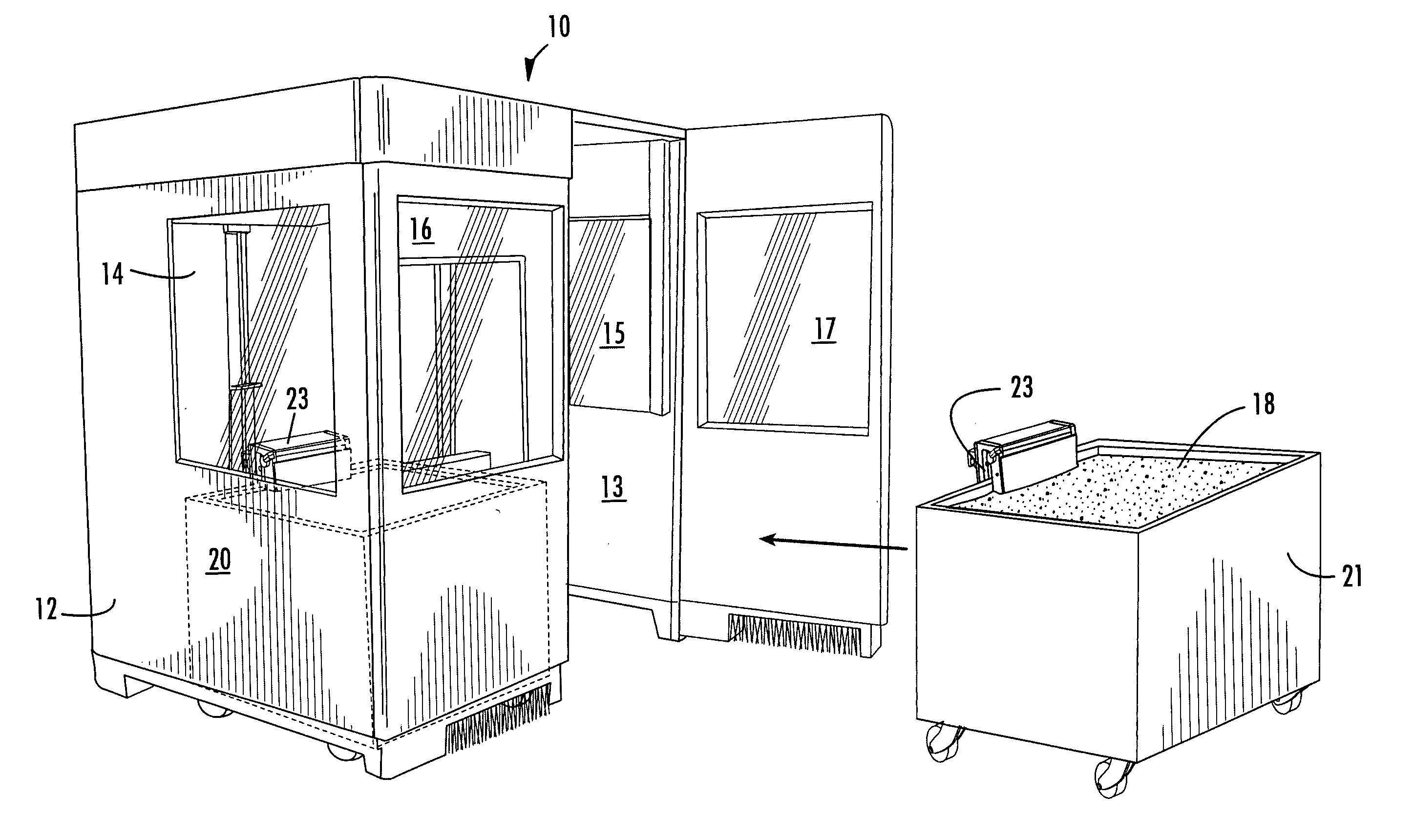
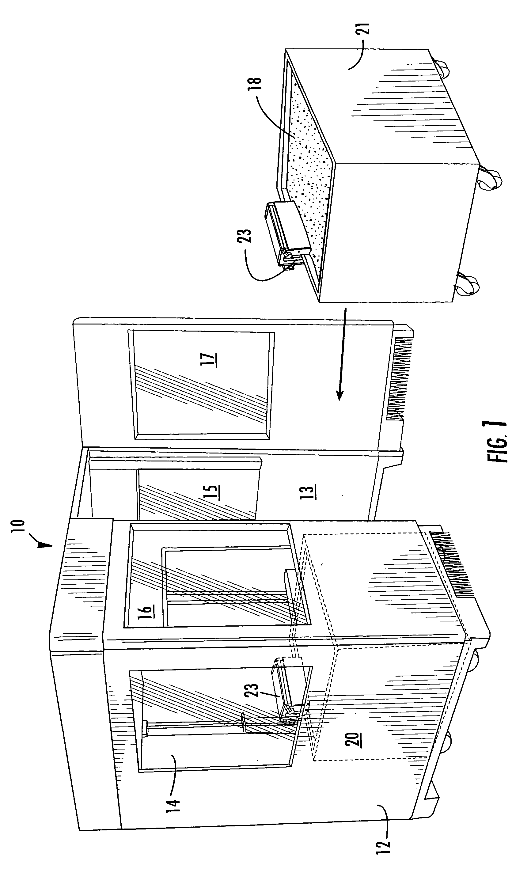
[0049] Turning now to FIG. 1, shown generally at 10 is a dual-chamber housing for housing two chambers 12, 13 for stereolithography. The housing has two chambers for increased efficiency of laser usage. While the object surface in one chamber is recoated, the laser can be applied to the recoated object surface in the other chamber so as to build objects in both chambers in a single run. The laser and the system for using the beam in multiple chambers is addressed in detail below.

[0050] The housing has view windows 14, 15 on opposite sidewalls, one in each chamber 12, 13, respectively. Each chamber has a door 16, 17 with a hingedly openable and removable ...


PUM

PropertyMeasurementUnit
stroke volumeaaaaaaaaaa
energyaaaaaaaaaa
thicknessaaaaaaaaaa

Abstract

A stereolithography apparatus having a resin vat with resupply containers in one-way flow communication and a leveling container in two-way flow communication, an automatic offload cart to remove and replace build support platforms, an elevator assembly for supporting and releasably retaining a build platform removably attached to the stereolithography apparatus frame such that elevator forks supporting the build platform can be released into the vat and removed from the stereolithography apparatus with the vat, and a recoater assembly and recoater blade for mapping the resin surface in the vat and applying a fresh coating of resin to a cross-section being built in the vat.

Description

BACKGROUND OF THE INVENTION [0001] This invention relates to methods and apparatus for rapid prototyping and manufacturing (“RP&M”) to produce three-dimensional objects, and more particularly to improving the productivity and efficiency of RP&M systems. [0002] RP&M is the name given to a field of technologies that can be used to form three-dimensional objects or solid images. In general, RP&M techniques build three-dimensional objects, layer-by-layer, from a building medium using data representing successive cross-sections of the object to be formed. Computer Aided Design and Computer Aided Manufacturing systems, often referred to as CAD / CAM systems, typically provide the object representation to an RP&M system. The three primary modes of RP&M include stereolithography, laser sintering, and ink jet printing of solid images. [0003] Laser sintering builds solid images from thin layers of heat-fusible powders, including ceramics, polymers, and polymer-coated metals to which sufficient ...

Claims


Application Information

Patent Timeline
Patent Type & Authority Applications(United States)
IPC IPC(8): B29C35/04
CPCB29C67/0062B29C67/0066B29C64/124B29C64/135B33Y40/00B33Y30/00B33Y10/00B29C64/182B33Y50/02
Inventor WAHLSTROM, BENSTONESMITH, MATTHEWHUNTER, DON FREDERICK
Owner 3D SYST INC
Why Eureka
Try Eureka