Digital programmable phase generator

a digital programmable phase and generator technology, applied in pulse manipulation, pulse technique, instruments, etc., can solve the problem of restricting the use of digital rsfq circuits in complex digital circuits

Active Publication Date: 2007-04-05
SEEQC INC
View PDF2 Cites 4 Cited by
  • Summary
  • Abstract
  • Description
  • Claims
  • Application Information

AI Technical Summary

Problems solved by technology

However, the lack of flexible programmability of these prior art phase generator circuits greatly restricted their use within complex digital RSFQ circuits.

Method used


Image

  • Digital programmable phase generator
  • Digital programmable phase generator
  • Digital programmable phase generator

Examples


Embodiment Construction

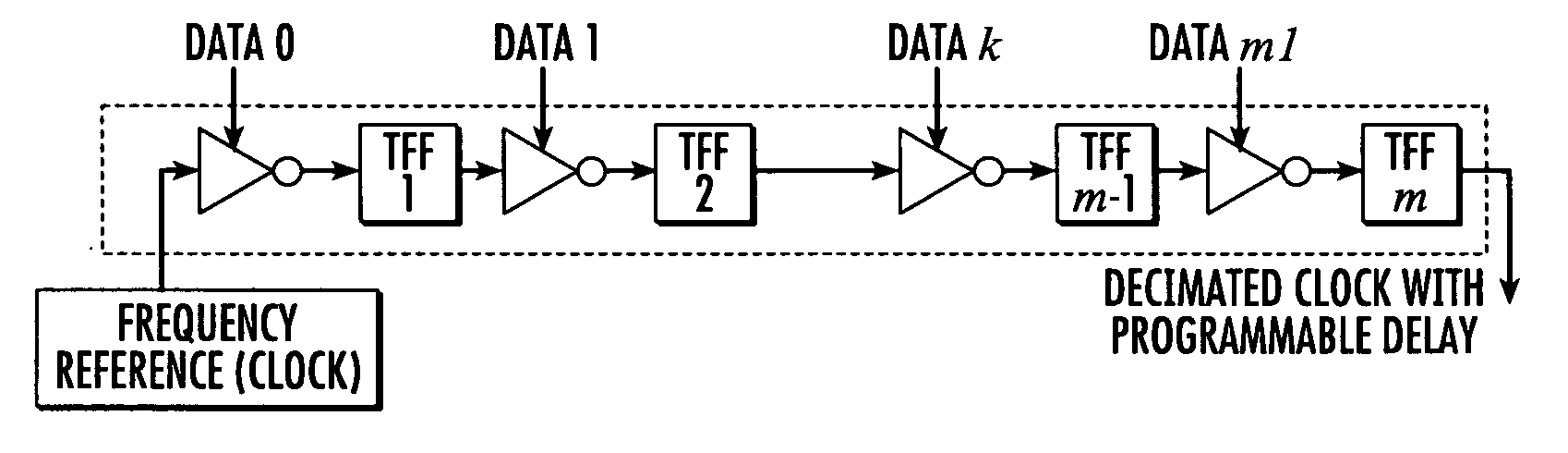
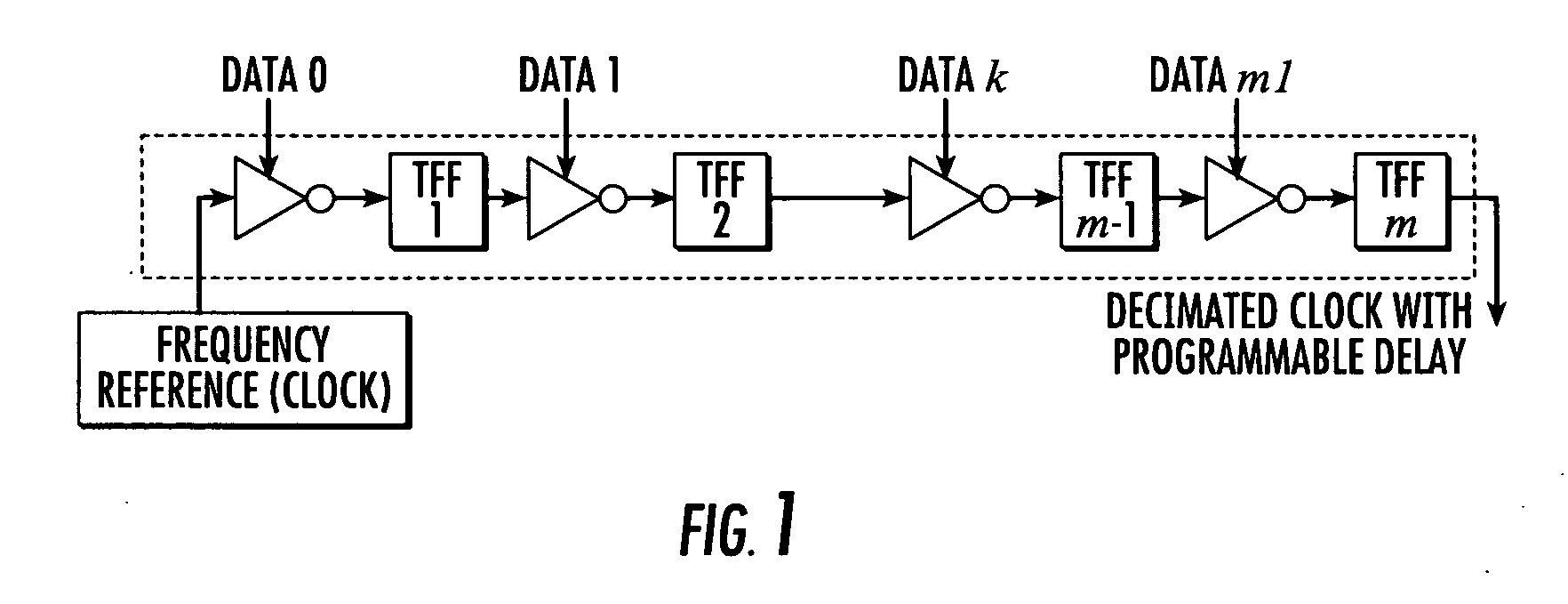
[0019]FIG. 1 is a block diagram of a programmable phase generator in accordance with one aspect of the invention. The programmable phase generator of FIG. 1 uses a Rapid Single Flux Quantum (RSFQ) binary counter comprising a chain of RSFQ toggling flip-flop (TFFs). It decimates the input periodic single-flux-quantum (SFQ) pulse signal by a factor of 2m, where m is the number of TFFs. By extracting an SFQ pulse from the k-th stage of the counter, the programmable phase generator delays the output signal by T·2k, where T is an input pulse sequence period. Thus, it achieves a phase shift of the output sequence by 2π·2k−m. In order to realize the functionality, an RSFQ inverter is inserted before each toggle flip-flop. The clock input and the data output of each inverter are connected to the output of the preceding TFF and the input of the next TFF respectively. In the absence of a data signal, an inverter stage forwards all clock pulses to its output. When an SFQ pulse is sent to the d...


PUM


Abstract

A programmable phase shifter is constructed of Rapid Single Flux Quantum (RSFQ) logic elements. The logic elements may include an RSFQ inverter and an RSFQ T flip-flop. A digital word comprising N bits is used to control the amount of phase shift and the phase shifter selectively imparts a respective phase shift for any of 2N states that can be represented by the digital word. The RSFQ logic elements utilize Josephson junctions which operate in the superconducting temperature domain.

Description

STATEMENT REGARDING FEDERALLY FUNDED RESEARCH [0001] This work was funded, at least in part, by ONR6.2D&I contract number N00014-02-C-0005.BACKGROUND OF THE INVENTION [0002] 1. Field of Invention [0003] The invention described herein relates to the field of superconductivity, and more specifically relates to circuits and techniques for implementing digital logic using Josephson junctions. [0004] 2. Related Art [0005] Josephson junctions are quantum-mechanical circuit elements of superconducting devices. The Josephson effect in particular results from two superconductors acting to preserve long-range order across a barrier, such as an insulating barrier. With a thin enough barrier, the phase of the electron wave function in one superconductor maintains a fixed relationship with the phase of the wave function in another superconductor. This linking up of phases is called phase coherence. [0006] A Josephson junction is the interface between two superconducting materials separated by a ...

Claims


Application Information

Patent Timeline
Patent Type & Authority Applications(United States)
IPC IPC(8): H03K19/195
CPCG06F5/08H03K3/38H03K5/131H03M1/82
Inventor KIRICHENKO, ALEXANDER F.
Owner SEEQC INC
Why Eureka
Try Eureka