Encapsulated transponder and method for manufacturing the same

a transponder and encapsulation technology, applied in the field of transponders, can solve the problems of conductive wire, small dimensions, and small filament size, and achieve the effects of good protection against stresses, shock, and easy removal from the connection

Inactive Publication Date: 2007-04-05
ASSA ABLOY AB
View PDF14 Cites 2 Cited by
  • Summary
  • Abstract
  • Description
  • Claims
  • Application Information

AI Technical Summary

Benefits of technology

[0022] It is another object of the invention to provide a simple and inexpensive method for manufacturing such a transponder.
[0030] A particular advantageous embodiment of the invention is to heat the transponder at a temperature higher than the fusion temperature of the coating liquid. This allows a faster and more uniform embedding of the transponder by the coating liquid.

Problems solved by technology

It is not always desirable, from an economical point of view, for a transponder manufacturer to perform all the production steps up to the final product.
However, following bonding of the conductive wire to the contact on the integrated circuit, the conductive wire, being filament-like and of small dimensions, may undergo shearing or fatigue caused by the filament pressing against the edge of the chip.
Such direct bonding configurations are particularly sensitive to mechanical stress and vibrations, as the integrated circuit is sometimes solely supported by the conductive wire.
However, in a great majority of the cases these processes result in very rigid systems, causing the conductor itself to break outside or at the edge of the encapsulation and thus disqualifying these methods for use in the manufacture of transponders.
Furthermore, encapsulations are expensive in practice because they involve a sequence of steps to prepare the integrated circuits for encapsulation.
In particular, they are multi-step processes that slow down the overall manufacturing process.
These processes also use a relatively large amount of additional material, as whole sheets of support or molds.
Unfortunately, such a process is not suitable for use in temporarily pre-packaging a transponder, as the resulting cured capsule is almost impossible to release without damaging the electronic circuit.
That makes it chemically and / or mechanically incompatible with particular final uses, including final packaging.
Photopolymerizable resins are expensive substances that are not chemically inert (previous to curing) and require special measures to be used in a manufacturing environment.

Method used


Image

  • Encapsulated transponder and method for manufacturing the same
  • Encapsulated transponder and method for manufacturing the same
  • Encapsulated transponder and method for manufacturing the same

Examples


Embodiment Construction

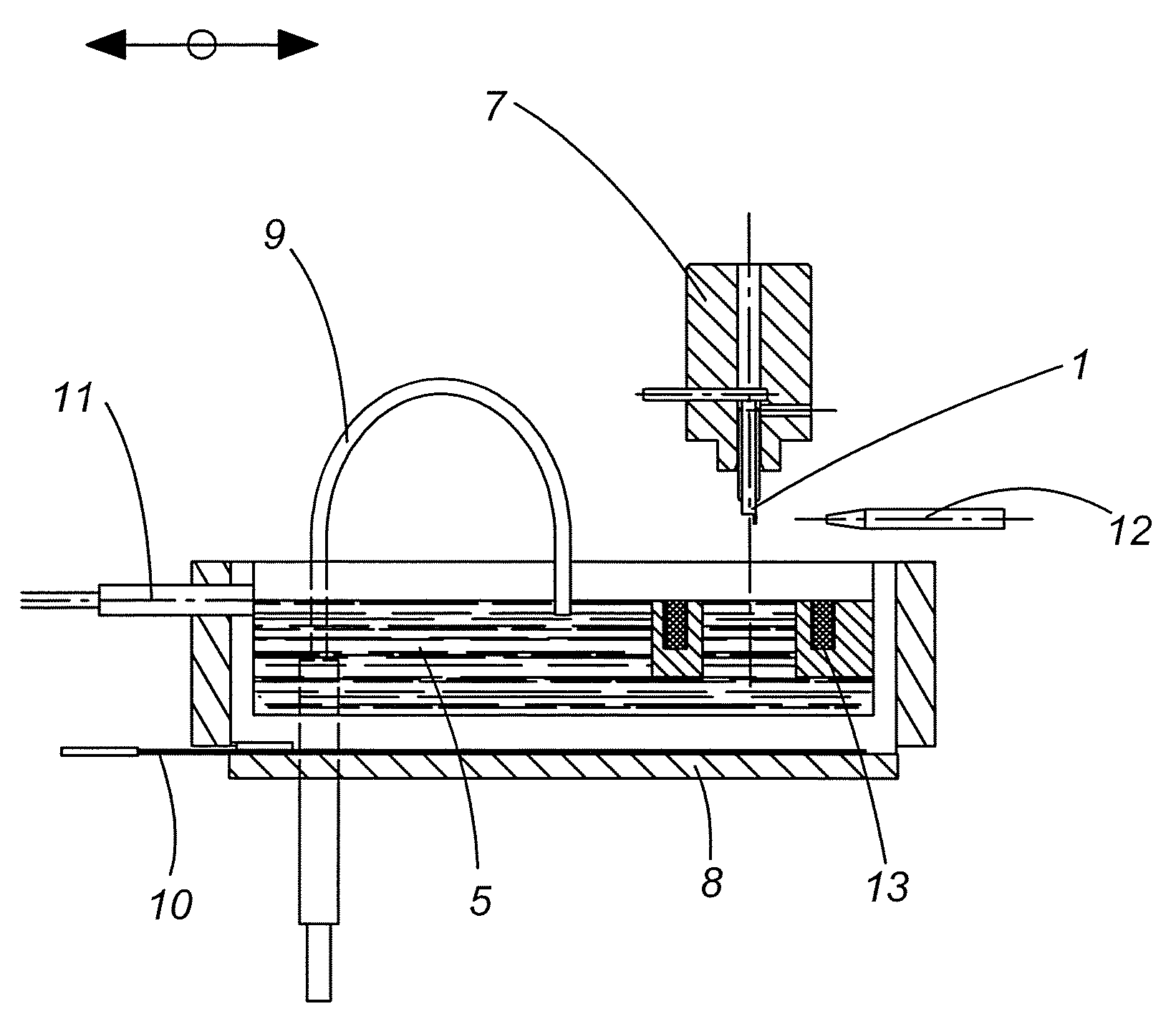
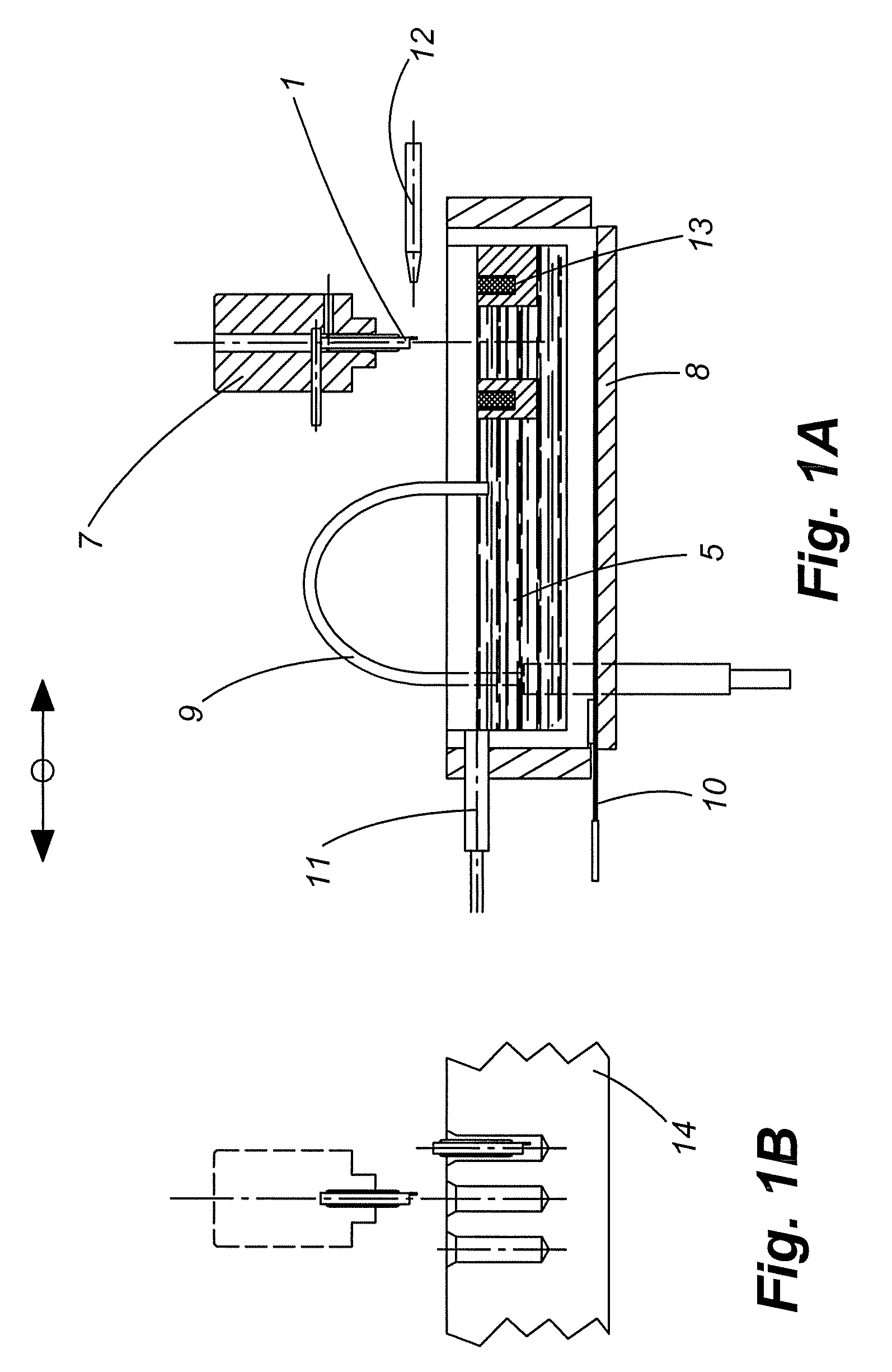
[0052] The embodiment shown in FIG. 1 comprises holding means 7, holding the transponder 1 in a vertical position above the coating basin 8. The holding mechanism could be, for example, a system utilizing magnets, vacuums, or a combination of both.

[0053] In one embodiment, the encapsulant or coating liquids in the coating basin8 is preferably a high temperature wax such as bees wax or a high temperature paraffin. The term high temperature means the melting temperature of the encapsulant is high. Concretely, a wax referenced Micro No 17 of ETS Jacques Vernet, with a fusion temperature of 86° C. can be used. To maintain a high homogeneity of the melted wax 5 during the process, the wax is maintained at a temperature of about 110° C. by way of a regulation temperature circuit comprising a thermocouple 9, a regulator (not shown) and a graphite heating body 10.

[0054] A laser detection means 11 is used to detect if the encapsulant or coating liquid 5 is below a given level. If the coati...


PUM

PropertyMeasurementUnit
temperatureaaaaaaaaaa
thickaaaaaaaaaa
pressureaaaaaaaaaa

Abstract

The invention concerns an encapsulated transponder (1) having an integrated circuit (2), an antenna (3) and one or more electrical connections (4) between the integrated circuit (2) and the antenna (3). At least a part of the transponder (1) comprising the electrical connections (4) is embedded within a capsule (6) that is removable without damaging the electrical connections (4). Also claimed is a method for the production of such a transponder (1).

Description

CROSS REFERENCE TO RELATED APPLICATIONS [0001] This Application claims the benefit of European Patent Application Number 05109156.9, filed Oct. 3, 2005, the entire disclosure of which is hereby incorporated herein by reference. FIELD OF THE INVENTION [0002] The invention relates to a transponder as installed primarily in devices for identification of objects of various types, including persons or animals, and to a method of encapsulating such transponders. More particularly, the invention relates to providing a removable capsule of encapsulating material around at least the connections between the ends of an antenna and an integrated circuit. BACKGROUND [0003] Transponders are well known in the art and generally comprise an electrical circuit having an antenna connected to an integrated circuit. The transponder is responsive to a received radio frequency signal and produces a radio frequency signal. [0004] Beside the connection of the two electric elements of the electrical circuit,...

Claims


Application Information

Patent Timeline
Patent Type & Authority Applications(United States)
IPC IPC(8): H04Q5/22
CPCB29C41/14B29C41/20G06K19/0723
Inventor ROBADEY, JEAN-MIGUELMEILLAND, ANDRE
Owner ASSA ABLOY AB
Why Eureka
Try Eureka