Display unit

a display unit and liquid crystal technology, applied in the field of liquid crystal panel display units, can solve the problems of deteriorating the character of the led itself, inability to obtain a sufficient light intensity as the backlight of the display unit, and inability to secure the long-term service life, so as to reduce brightness irregularities and efficient heat radiating

Inactive Publication Date: 2007-04-05
HITACHI LTD
View PDF5 Cites 127 Cited by
  • Summary
  • Abstract
  • Description
  • Claims
  • Application Information

AI Technical Summary

Benefits of technology

[0060] In accordance with the present invention, there can be provided an LED backlight type display unit which efficiently radiate heat generated i...

Problems solved by technology

In the conventional display unit, since a heat radiation of the LED is not sufficient, the LED comes to a high temperature, so that there is a problem that the characteristic of the LED itself is deteriorated such as a light output is lowered, a long-term service life can not secured, or the like.
Accordingly, it is necessary to descend the current value for suppressing the heat generation in order to maintain the characteristic of the LED itself, and it is impossible to obtain a sufficient light in...

Method used


Image

  • Display unit
  • Display unit
  • Display unit

Examples


first embodiment

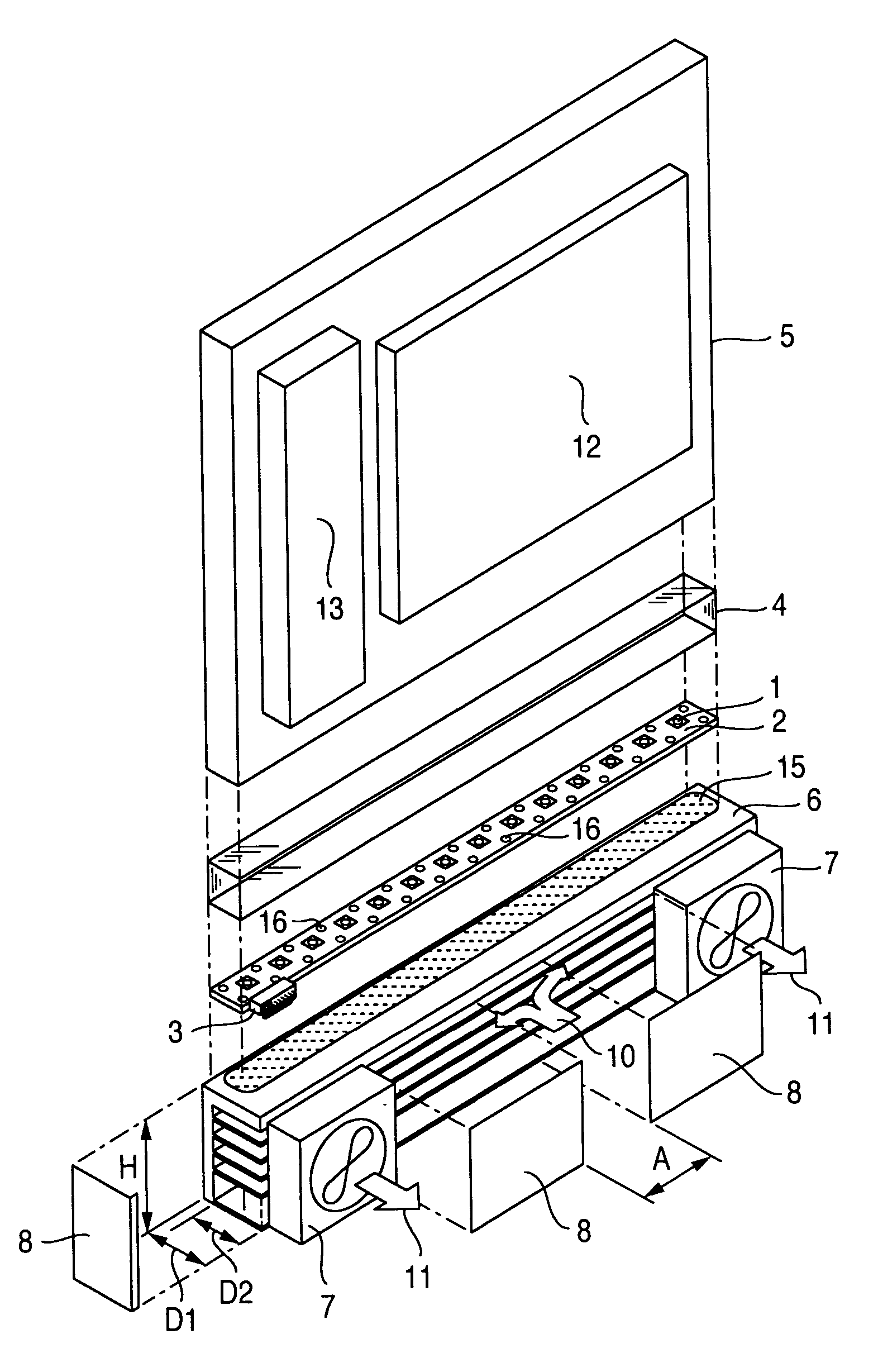
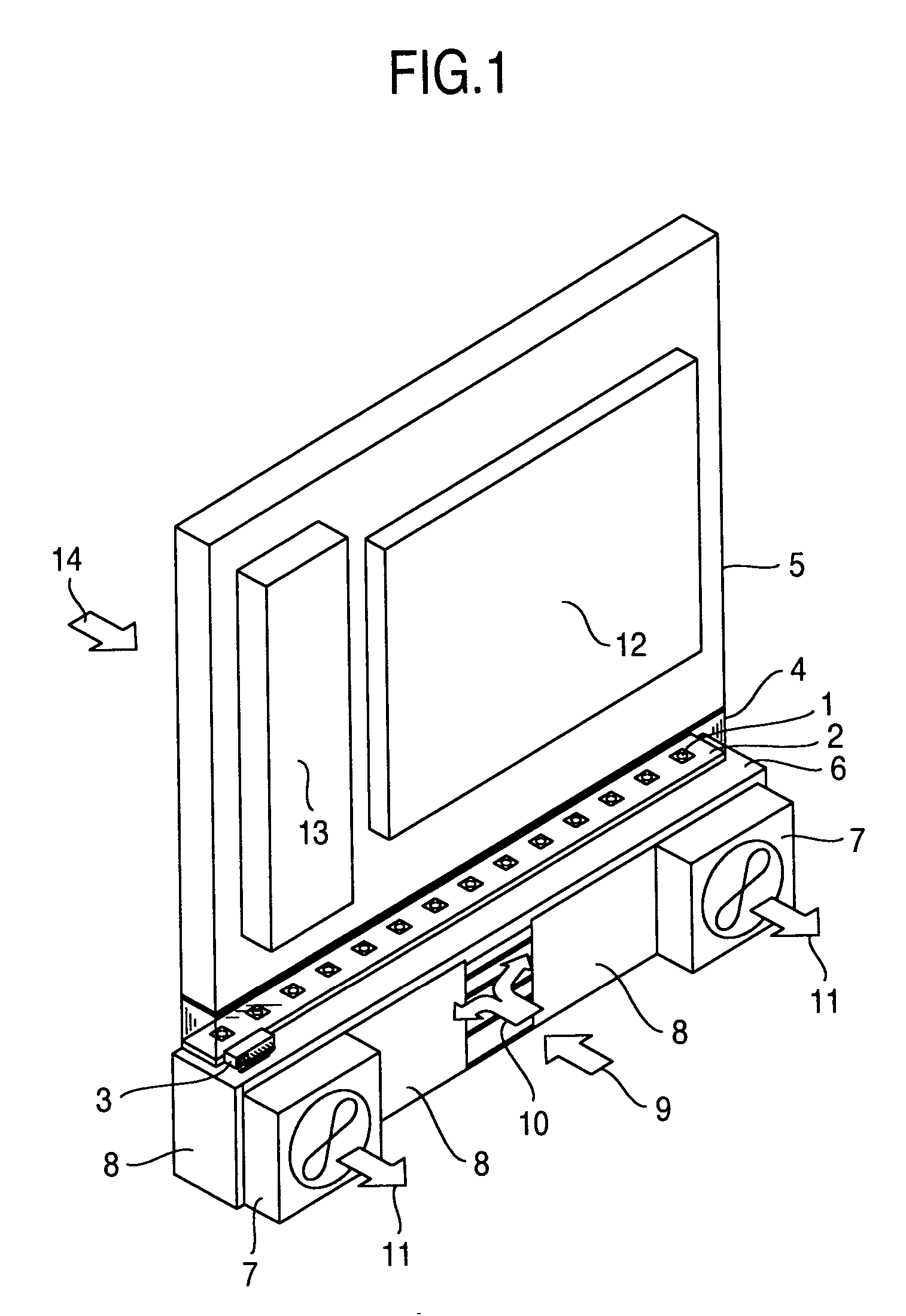
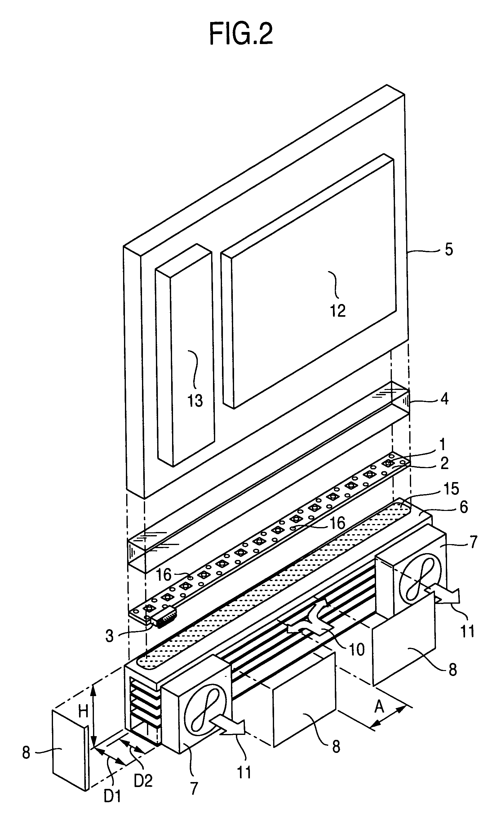
[0068] A description will be given below of a first embodiment with reference to FIGS. 1, 2, 3 and 4.

[0069] In recent years, the LED has an increased luminous efficiency, attracts attention as a backlight light source for a liquid crystal display having an improved color reproduction performance and is developed in many fields such as a field for a display of a personal computer, a filed for a liquid crystal television set and the like. However, at this time, the luminous efficiency is lower in comparison with a fluorescent cold cathode tube system corresponding to the present major backlight system, and a great current is necessary for obtaining the same brightness. Accordingly, there is a problem that a heat loss, that is, a calorific power in the LED becomes great.

[0070] The present invention achieves a structure for efficiently radiating the heat generated in the LED to the ambient air.

[0071]FIG. 1 is an internal perspective view of a display unit provided with a first embodim...

second embodiment

[0095] A description will be given below of a second embodiment with reference to FIG. 5.

[0096]FIG. 5 is a perspective view of a heat sink used in a display unit provided with the second embodiment in accordance with the present invention.

[0097] In FIG. 5, in the present embodiment, the other structures than the heat sink 6 are the same as those of the first embodiment in accordance with the present invention, and a difference within the heat sink 6 exists in a structure in which a plurality of fins formed in the base portion are constituted by pin-type fins 19. In the same manner as the first embodiment, the material of the heat sink 6 is preferably constituted by the aluminum or the copper, and it is preferable that a pin diameter P of the pin fin 19 is set to 0.5 to 1.0 mm. Further, in the same manner as the first embodiment, the pin fins 19 are arranged approximately in parallel to the base surface on which the substrate is mounted, in the same manner as the first embodiment.

[...


PUM


Abstract

In the case that the LED is used as a light source for a backlight such as a display unit or the like, if a lot of current is circulated for securing a brightness, a lot of heat is generated in view of a characteristic of the LED, so that the LED comes to a high temperature, and there is a problem that the characteristic of the LED itself is deteriorated such as a light output is lowered, a long-term service life can not secured, or the like. Further, in the case that a temperature difference exists between a plurality of LEDs, there is a problem that it appears as a brightness irregularity of a screen of the display unit. The display unit is provided with a heat sink attached so as to be thermally contacted with an opposite side to an LED mounting surface of a substrate on which the LEDs are mounted, and one or a plurality of fans, a base portion of the heat sink has a substrate mounting surface and a fin constituting surface, the fin constituting surface is approximately perpendicular to the substrate mounting surface, and the fin constituting surface of the base portion and an air supply and exhaust surface of a cooling air are formed in an opposite side to a screen display side of the display.

Description

BACKGROUND OF THE INVENTION [0001] 1. Field of the Invention [0002] The present invention relates to a liquid crystal panel type display unit using a light generating source such as an LED or the like as an edge light type backlight. [0003] 2. Description of Related Art [0004] As a prior art of an edge light type backlight system using an LED or the like as a light generating source, for example, there is patent document 1 (JP-A-2005-38771). [0005]FIG. 6 is a view citing a drawing in the patent document 1. [0006] In FIG. 6, the display unit is provided with a plurality of LEDs 31 corresponding to a light source, and an LED substrate 32 mounting the LEDs 31 thereon. The display unit is provided with a diffusion plate 34 irradiating the light of the light source emitted from an incident surface in a side surface as a surface light source from an irradiation surface in a front surface, and a display board case 37 accommodating the LEDs 31, the LED substrate 32 and the diffusion plate, ...

Claims


Application Information

Patent Timeline
IPC IPC(8): F21V7/04
CPCG02B6/0068G02B6/0073G02B6/0085G02F1/133615G02F2001/133628G02F1/133628
Inventor ATARASHI, TAKAYUKITERAKADO, SHUICHIAKAI, HIROSHIYOTSUMOTO, NAOKI
Owner HITACHI LTD
Why Eureka
Try Eureka